SDS1000X-E&SDS1000X-U User Manual
100
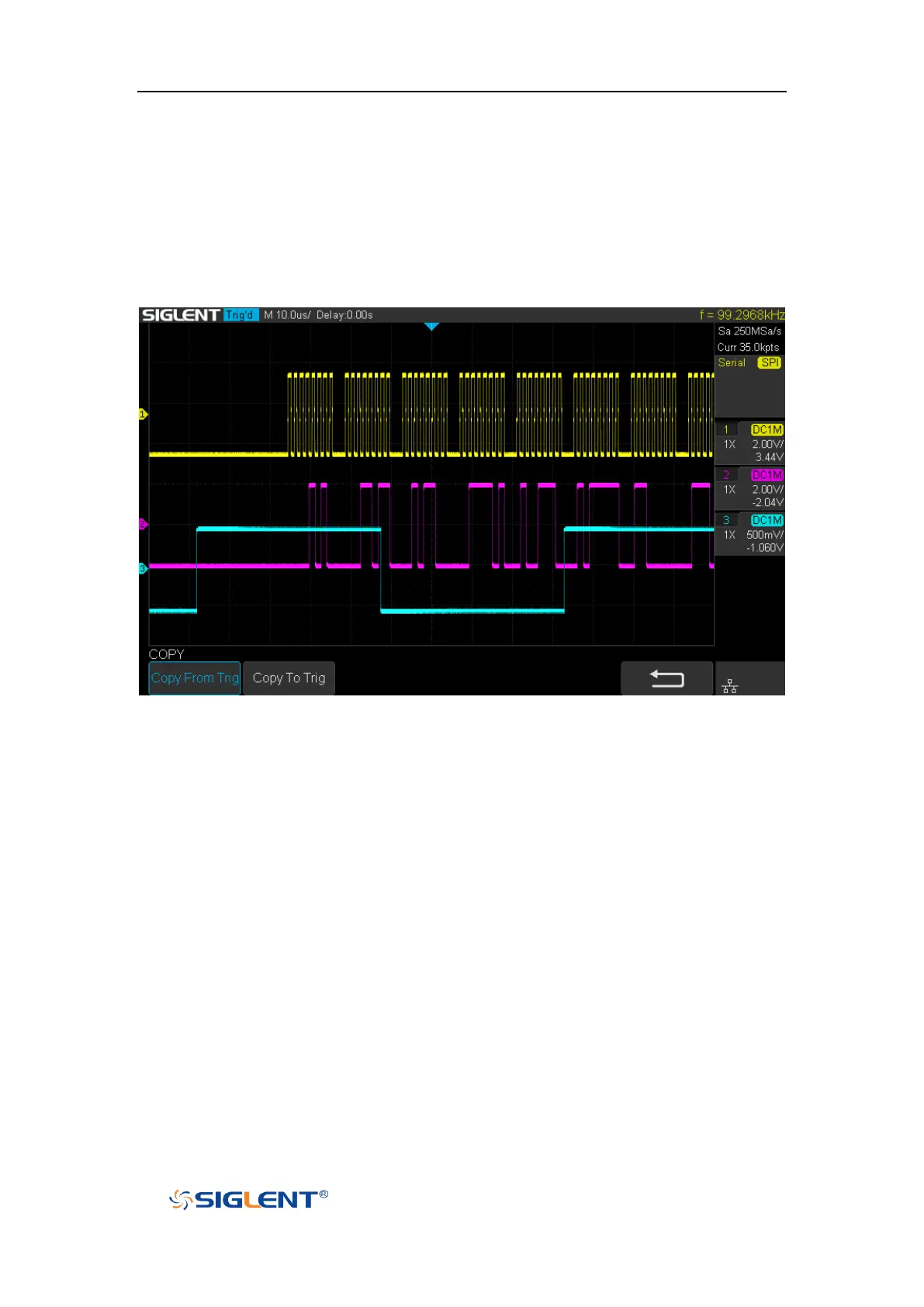
Example:
Connect the data, CLK and ~CS signals of a SPI bus respectively to C1, C2 and C3.
Data width = 8-bit, Bit order = MSB, CS polarity = ~CS, and 12 data bytes are
transmitted in one frame.
In the SPI trigger signal menu, set the source and threshold of CLK, MISO and CS
signals, then copy the trigger settings to decoding. Adjust the timebase, so that
there is a falling edge on CS signal shown in the screen:
When the CS type is set to Clock Timeout, the clock idle time between frames is T3,
the clock period is T1, then set the timeout to a value between T1 and T3: