1-2
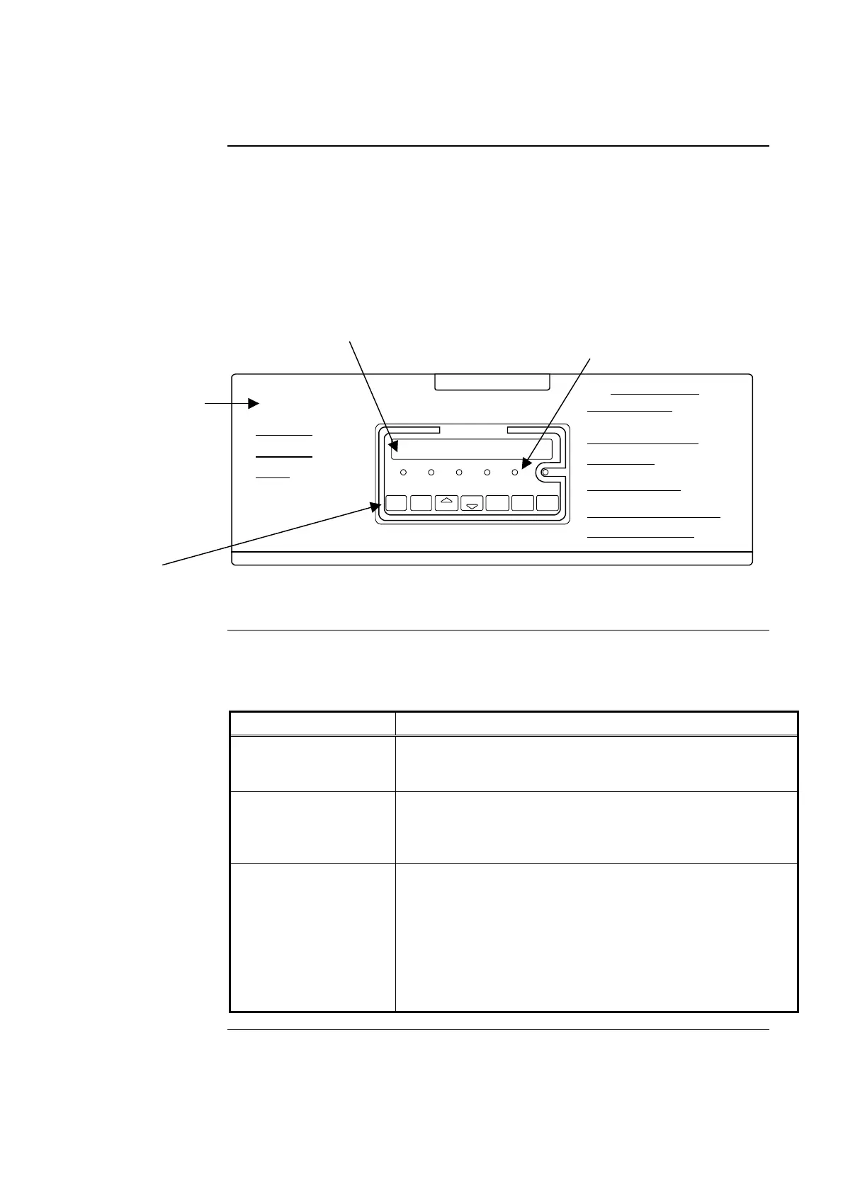
When the panel access door is in the up position, as shown in Figure 1-1, the keys,
alphanumeric display, and indicators that appear are referred to as the Firefighter facility. It is
the area in the center of the panel with the red line containing the text “FIREFIGHTER
FACILITY.” The Firefighter Facility is an AS 4428-compliant interface that provides
firefighters with a standard set of alarm displays and controls for use in managing fire alarm
conditions.
The components of the Firefighter Facility – Indicators, Alphanumeric display, and Firefighter
Facility keys – are discussed in separate sections below.
SYSTEM IS NORMAL
EXT BELL
ISOLATE
ALARMWARN SYS
FIREFIGHTER FACILITY
ISOLATEFAULT
08:23:43 am
EXT BELL
ISOLATE
WARN SYS
ISOLATE
PREV
NEXT
ACK ISOLATERESET
POWER
PRESS LATCH TO OPEN DOOR
OPERATOR INSTRUCTIONS
OPERATOR
INTERFACE
PANEL
FIREFIGHTER INTERFACE
To Acknowledge ALARM conditions:
•
•
To Review Alarms without acknowledging them:
•
To Reset an Alarm condition:
To Isolate/De-Isolate an Alarm condition:
To Isolate/De-Isolate the External Bell or Warning System:
For Faults and other service-related functions:
Press ACK to acknowledge Alarm and silence sounder (next
unacked alarm is displayed).
First unacked Alarm is displayed (Alarm LED indicator is flashing).
•
Repeat sequence until all alarms are acknowledged (LED steady).
•
Press NEXT to view next (more recent) alarms.
Press PREV to view previous (older) alarms.
•
Press RESET key with desired alarm in the display.
•
Press ACK to confirm, or any other key to cancel.
•
Point will clear if cause of alarm has returned to normal.
•
Press ISOLATE key with desired zone in the display.
•
Press again to toggle requested state (ISOLATE/DE-ISOLATE):
•
Press ACK to confirm, or any other key to cancel.
•
Press associated key to toggle current isolate state.
•
Indicator above key illuminates when associated output is isolated.
• Open access door and follow instructions on inside label.
THUR 16 NOV 00
Figure 1-1. Operator Interface – Panel Access Door Up Position
Table 1-1 provides an introduction to the indicators located on the Firefighter Facility.
Table 1-1. Firefighter Facility Indicators
Indicator State Description
EXT BELL Isolate
Indicator
Indicator On Steady. Indicates the FIP’s External Bell
output is isolated. The bell connected to this output identifies
the building location nearest the FIP to the fire brigade.
WARN SYS Isolate
Indicator
Indicator On Steady. Indicates the FIP’s Early Warning
System (EWS) output is isolated. The EWS consists of horns
and strobes used to notify building occupants that an alarm
condition exists.
Alarm Indicator
Indicator Flashing. Indicates the presence of an
unacknowledged alarm condition; refer to Chapter 2 for
information on acknowledging alarms.
Indicator On Steady. Indicates the presence of an alarm
condition that has already been acknowledged by an
operator. The condition causing the alarm must clear and the
alarm must reset before the panel can return to normal.
Refer to Chapter 2 for information on resetting an alarm.
Continued on next page
Door Up – Firefighter Facility Operator Interface
Introduction
Indicators
Panel
Access
Door
Indicators
Alphanumeric Display
Firefighter
Facility Keys