Chapter: 4. Installation
4. Installation
Standard System Supply
A basic GDS101 system consists of the following units:
(See “Fig. 4.1. Basic System Conguration.” on page 36).
• Operator unit with installation material.
• Transducer junction box(es). See “Fig. 4.2. Transducer Junction Box.” on page 37.
• Approved transducer steel tank(s) or sea valve(s).
• Transducer(s) and mounting.
• Operation and installation manual.
Transducer Installation
Location
• A transducer should be installed in an area securing optimal measurement free from noise and
aeration.
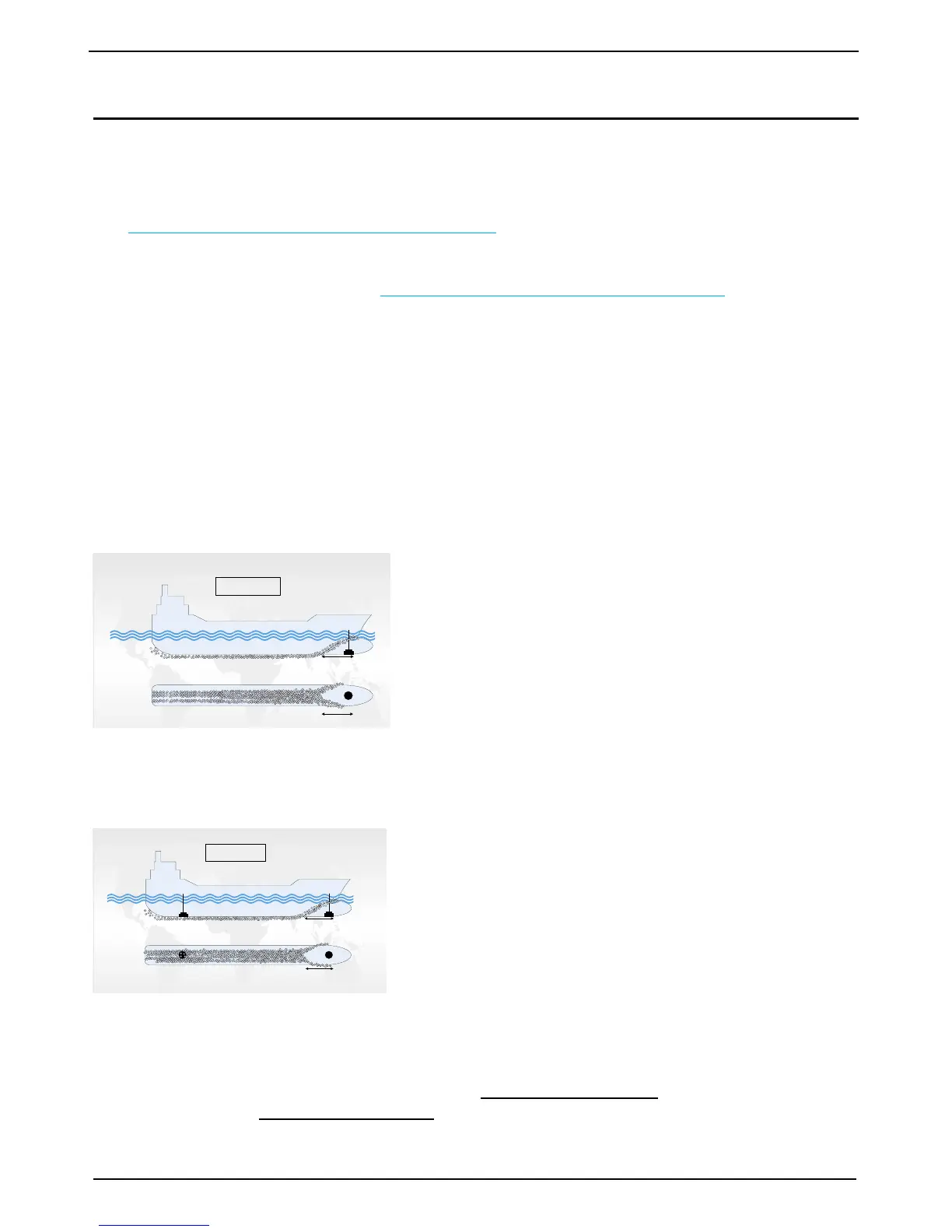
• Transducers are normally installed in the noise free area in the foreship (see A on g.)
Optimal system operation is achieved by tting the transducer
as deep as possible on the hull. The transmitting surface of the
transducer must be installed horizontally.
Do not mount transducers close to the propeller or aft of other
hull installations (outlets, vents or other protruding details). It is
necessary to select a part of the hull that is submerged under all
load and speed conditions, and to avoid positions where air is
trapped in heavy weather.
If a at, horizontal section is not available for transducer tting, the shipyard must construct a suitable bed.
Larger vessels are often tted with two transducers, one fore and one aft (see g.)
The fore transducer is the primary transducer, (normally 50 kHz).
The aft transducer is a secondary transducer, (normally 200 kHz).
The aft transducer will be troubled with aeration and noise and
will not operate in speed >4-5 knots. It is used to measure aft
depth in shallow water.
Installation Details
Refer to SKIPPER’s installation procedures in the appendix and
on our web site www.skipper.no regarding information about sea valve, tank installation, welding, cable
glands etc.
Note:
• Protect the active element of the transducer and do not paint the surface.
• Transmission in the air must be avoided! This may cause mechanical damage of the element.