Chapter: 3. User Maintenance
Typical Oscilloscope Screen (10) Contents
Filter width:
Peaks with smaller
distance are considered one
print
SCREEN
Ping 795mcS
Delay 1253mcS
Receiv. 333mcS
Bot. strength 226
PRF 2
Gain 20
Frq 50
Bottom window 20%
Leading front 40%
Filter width 15cm
Min amplitude 24
Ping (10m) 150micS
Ping (500m) 3000micS
Delay (10m) 350micS
Delay (500m) 3000micS
20%
25%
TVG
N 13°13.20' E 079°44.5' 14kts 145° 0 m
15:03 GMT
200m PICT.SPEED 0:08/div SCREEN 10
20 mS/div
80
160
50
100%
POWER
Bot(tom). strength
Leading front
70% of previous bottom strength
(minimum tracking requirement for
next)
Bottom window
Dynamic after-ring cutoff.
(< Minimum amplitude)
Minimum amplitude
Current depth
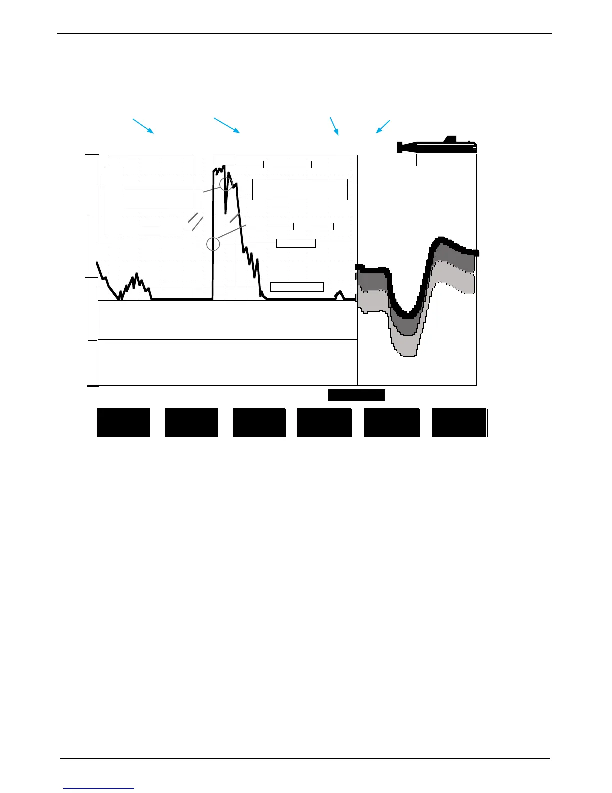
Fig. 2.11 Screen 10, Oscilloscope Screen.
This screen shows oscillogram of receiver output versus time and half screen echo-gram.
Soft Key 1. PRINT screen Print screen.
Soft Key 2 not used
Soft Key 3 not used
Soft Key 4. GAIN 0 - 100% Gain Adjustment.
Soft Key 5 TVG 0 - 100% Time Variable Gain Adjustment.
Soft Key 6 POWER 0 - 100% Transmitter power adjustment.
This oscilloscope screen 10 shows a typical oscillogram of a bottom echo (the tall peak in the centre of the
diagram) and a weaker sh echo to the left of it. The horizontal axis represent time for the sound to travel
down and back from an object. The vessel is located at the left edge of the grid, and the right edge represent
the depth range. The vertical axis represent the magnitude of the echo signal received.
The length of the ping and the delay between pings, will adjust between preset limits (ping (10 m) and ping
(500 m)). The actual length of these extremes are shown here.
Time indication,
manual or from GPS
Position from GPS
Speed indication from
GPS/speed log
Heading indication
from GPS
GDS101 Operation and Installation
SKIPPER Electronics AS