Chapter: 4. Installation
Interfacing
Alarm relay
An alarm relay is provided for interconnection to external alarm systems. This relay is normally
energised, and is released by alarm conditions or power failure/power off. See “Fig. 4.7. Main
Wiring Diagram.” on page 43, and “Fig. 4.8. Input/Output Circuitry.” on page 44 and “Fig. 4.11. Alarm
interconnections” on page 48. The terminals have the following signicance:
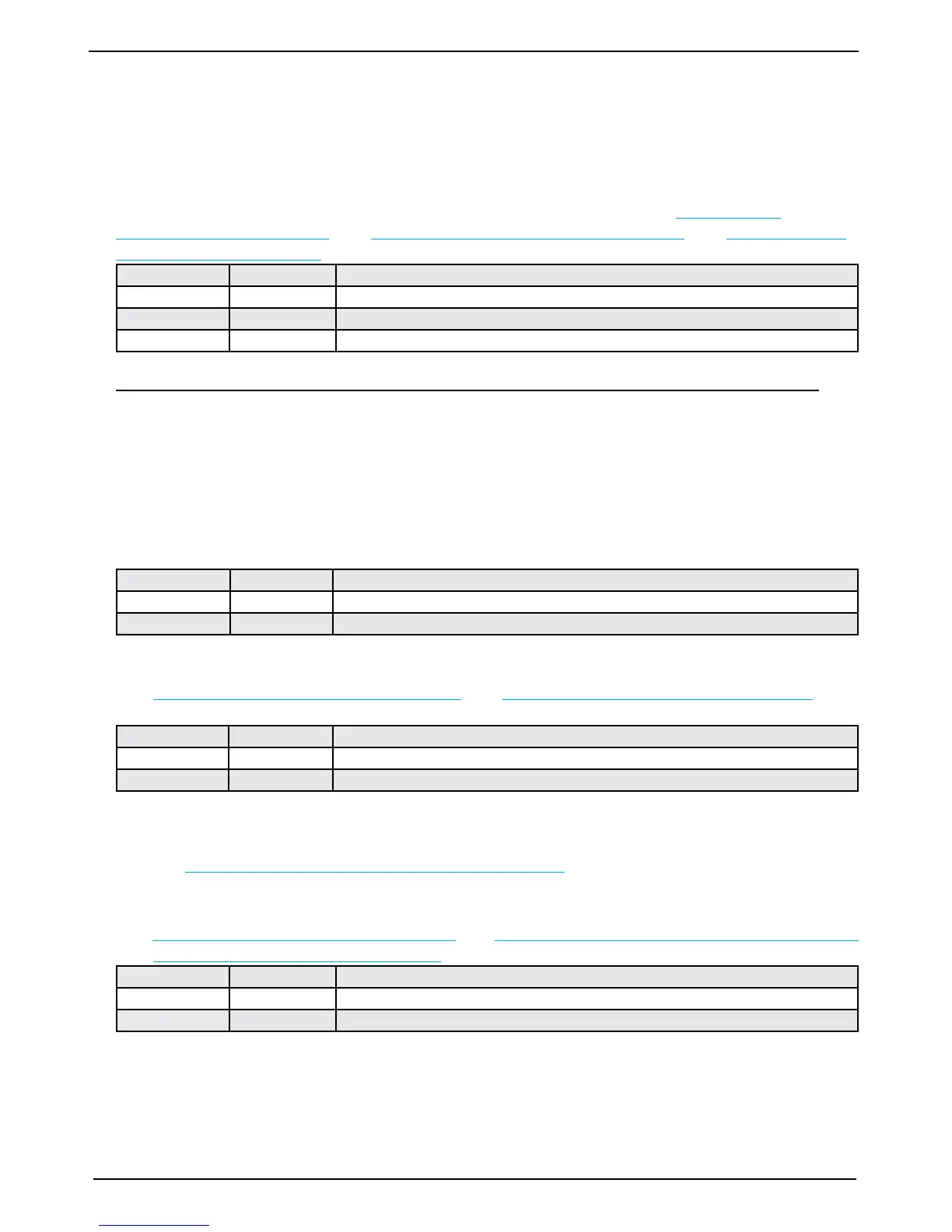
Name J100 pin no Description
ALCOM 3 Common terminal.
ALNO 4 Normally open contact.
ALNC 5 Normally closed contact (Normal = “No alarm” condition).
To comply with MED rules, it is mandatory to connect this output to an audible alarm system.
External alarm reset function
• Can be connected at Keyb+/Keyb-, in parallel with external keyboard (if attached).
• External reset will disengage alarm relay and reset audio alarm (if enabled).
• Visual alarm (blinking digital depth indication on the right side of the screen) is not affected and must
be reset locally by pressing any key on the panel.
External alarm reset terminals are as follows:
Name J100 pin no Description
KEYB+ 10 External alarm reset control input +.
KEYB- 11 External alarm reset control input -.
Log Pulse input
See “Fig. 4.7. Main Wiring Diagram.” on page 43 and “Fig. 4.8. Input/Output Circuitry.” on page 44. Pulse
input terminals are as follows:
Name J100 pin no Description
100/200 + 6 Log pulse input +.
100/200 - 7 Log pulse input -.
If speed pulses are received on pin 6 -7 while VTG (Track and ground speed) values are received on the
NMEA input, it is the pin 6 - 7 values that are shown as speed indication on top of the screen. If these
pulses are removed, the NMEA value will be displayed instead.
Refer to “Fig. 2.7. Screen 6, Interface setup screen.” on page 18 for selection of the log pulse rate.
Remote Transducer Selector FEEDB (Feedback)
See “Fig. 4.7. Main Wiring Diagram.” on page 43 and “Fig. 9.1 Transducer Selector Connection” on page 62
and “Fig. 9.2 Transducer Selector” on page 63. Transducer selector control input terminals are as follows:
Name J100 pin no Description
STPRINT + 8 Transducer control input +.
STPRINT - 9 Transducer control input -.
Transducer selector FORWARD position: (open - FORWARD/PORT transducer selected).
Transducer selector AFT position: (closed - AFT/STARBOARD transducer selected).