Chapter: 2. Operation
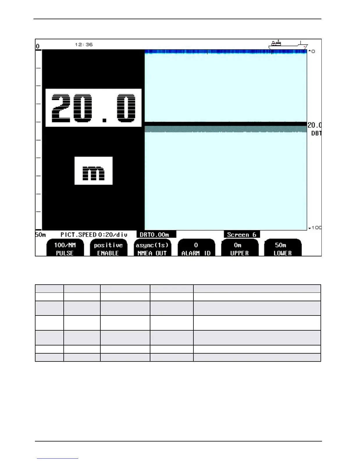
Fig. 2.7. Screen 6, Interface setup screen.
This screen shows the main graphic echo gram. Left hand digital indication may be enabled from screen 2.
Soft key Name Range/value Default value Description
1
PULSE 100/200/400/20000 100/NM Speed log input pulse rate. (Pulses per nautical mile).
2
ENABLE
(option)
Positive/negative Positive Select polarity of external sync signal (remote sounding
control option).
3
NMEA OUT async (1s)/
(sync)hronous
async (1s) Select between synchronous (with sampling rate) and
asynchronous (1s period) NMEA output update.
4
ALARM ID 0 - 999 0 Alarm identier, used in NMEA alarm sentences to be
uniquely recognized by the listener.
5
UPPER 0 - 199 m 0 m Analogue output shallow water limit = 0 V (4 mA).
6
LOWER 1 - 200 m 50 m Analogue output deep water limit = 10 V (20 mA).
Note: Soft key 2 controls optional function.