Chapter: 4. Installation
F
1
E
D
32
C
B
A
1
2 3
4
File name
Title/Name, designation, material, dimension etc
Checked by
Itemref
Designed by
Quantity
76
Approved by - date
8
Article No./Reference
Date
Edition
Sheet
Scale
F
E
D
5
RevNo
Revision note
6 7
C
B
Checked
8
Date
Signature
A
TB-3018-Rev-01
SKIPPER Electronics AS
A.Matre
14.01.2010
1206
1/1
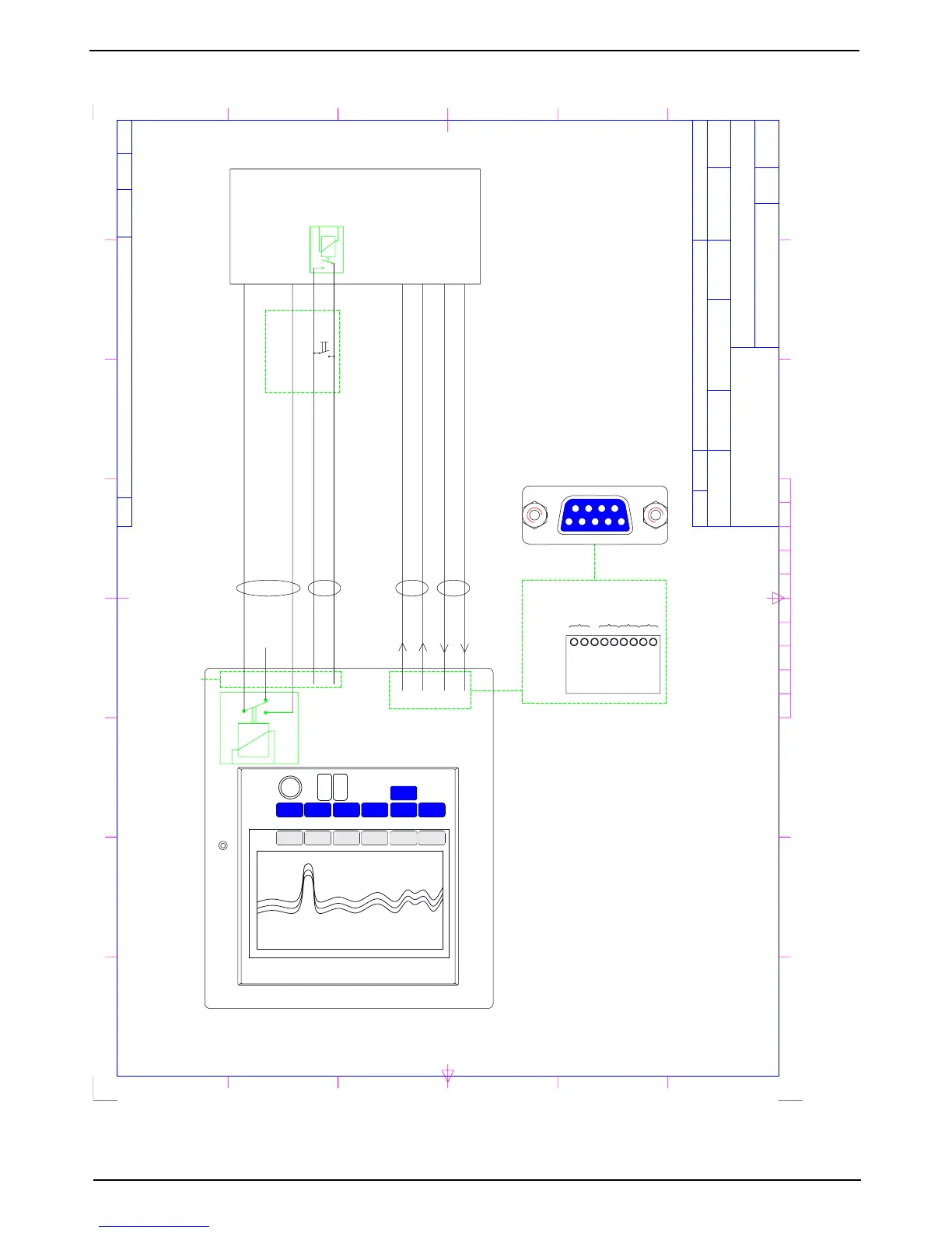
INTERCONNECTION POSSIBILITIES WITH ALARM SYSTEMS
Display/Operator Unit
Alarm System
Alarm Reset
Relay
AL NC
Combined functions & Power failure Alarm
AL NO
AL COM
Keyb +
Keyb -
5
4
3
Alarm reset +
Alarm reset -
J 100
10
11
Ext. Alarm reset
Connector
Interconnection possibilities with
Alarm Systems GDS 101
Female
XJ 402
5
9
8
7
6
4
3
2
1
Interface Connector
NMEA 0183
Output 2
Input 2
Output 1
Input 1
9
8
7
6
5
4
3
2
1
XMT2B
XMT2A
RCV2B
RCV2A
XMT1B
XMT1A
RCV1B
RCV1A
XJ 402
2,7
1,6
5,9
4,8
#XXACK, <ID>
NMEA IN
#XXALR, <TIME>, <ID>, <MESSAGE>
NMEA OUT
B
A
B
A
Fig. 4.11. Alarm interconnections