Chapter: 4. Installation
Options
Repeaters/Slaves
Graphic CRT (VGA), LCD displays or digital depth slave repeaters may be connected to the system. Along
with the graphic display repeaters, there may also be installed remote keyboard. The graphic repeaters
require the installation of line driver units dependant on the distance between the main system and the
repeater. See “Fig. 4.7. Main Wiring Diagram.” on page 43 and “Fig. 4.10. Data Communication Interfaces.”
on page 47.
Remote Keyboard
The unit may optionally be operated from a remote keyboard/hand controller. See “Fig. 4.7. Main Wiring
Diagram.” on page 43
Name J100 pin no Description Hand controller cable colour
KEYB+ 10 Keyboard signal. Blue.
KEYB- 11 Keyboard reference. Yellow and black.
INHIB+ (+12 V DC) 12 Keyboard power. Red.
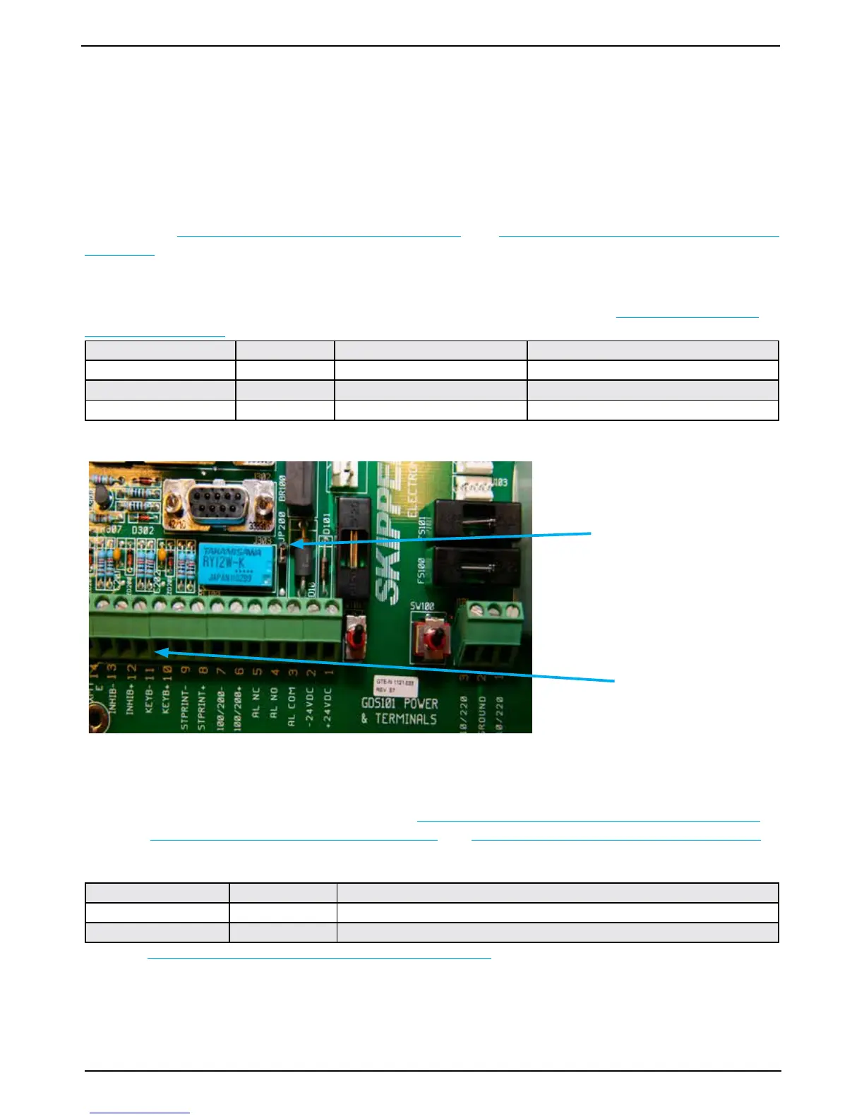
Note: When connecting remote keyboard/hand controller, make sure jumper JP200 is present on the Power
terminal board. This jumper provides +12 V DC to J100 pin 12 (INHIB+).
Remote Sounding Control.
This option lets the GDS101 being controlled remotely in synchronised (edge), burst (level) or single ping
modes. If installed, these options are accessible on “Fig. 2.4. Screen 3, 3rd Operation screen.” on page 15.
Also see “Fig. 4.7. Main Wiring Diagram.” on page 43 and “Fig. 4.8. Input/Output Circuitry.” on page 44.
Sounder remote control terminals are as follows:
Name J100 pin no Description
INHIB + 12 Control Signal Input +.
INHIB - 13 Control Signal Input -.
Refer to “Fig. 2.7. Screen 6, Interface setup screen.” on page 18 for selection of the control signal polarity.
Note: With the present hardware, it is not possible, at the moment, to use “Remote Keyboard” and “Remote
Sounding Control” (Navy option) simultaneously.
Location of jumper
JP200 on Power
terminal board.
Hand controller
connection