Chapter: 4. Installation
Transmitter trigger pulse and bottom pulse outputs
These outputs can be used to connect a repeater e.g. SKIPPER IR201, or to synchronize other
hydroacoustic equipment to avoid interference. See “Fig. 4.7. Main Wiring Diagram.” on page 43 and “Fig.
4.8. Input/Output Circuitry.” on page 44. Pulse output terminals are as follows:
Name J100 pin no Description
XMIT E 14 Emitter of output opto coupler, transmitter trigger pulse.
XMIT C 15 Collector of output opto coupler, transmitter trigger pulse.
BOTTOM E 16 Emitter of output opto coupler, bottom pulse.
BOTTOM C 17 Collector of output opto coupler, bottom pulse.
Analogue interfaces
GDS101 is equipped with analogue outputs to supply analogue repeaters or other equipment with
analogue inputs. See”Fig. 4.7. Main Wiring Diagram.” on page 43. The signals are galvanically connected
to the GDS101. See “Fig. 4.8. Input/Output Circuitry.” on page 44. Standard range is 0 - 10 V or 4 - 20
mA corresponding to shallow (UPPER) and deep (LOWER) settings. These settings may be accessed
on “Fig. 2.7. Screen 6, Interface setup screen.” on page 18. Analogue outputs from the GDS101 have the
following signicance:
Name J100 pin no Description
ANA 10 V 20 Positive analogue voltage output.
ANA REF 21 Negative analogue reference.
ANA 20 mA 22 Positive analogue current output.
ANA REF 23 Negative analogue reference.
NMEA interface
The NMEA outputs provides IEC 61162-1:2007(E) (NMEA 0183) format depth information to other
equipment with NMEA 0183 inputs. Baud rate is 4800 or 9600, 8 bit, no parity. Several messages
may be selected on “Fig. 2.9. Screen 8, NMEA control screen.” on page 20 and the enabled messages
are transmitted every second. The NMEA inputs accept position, speed, alarm, heading and UTC time
messages from various navigators, compasses or speed logs. The two inputs provided may be connected
to different talkers, and both data streams will be received. There are two outputs (both from COM 1)
that will drive each minimum of 10 standard NMEA 0183 inputs.
Note: Screen 8 NMEA control screen shows in the text window received or transmitted messages on the
presently selected channel (COM 1 or COM 2).
The NMEA 0183 outputs and inputs are available on the XJ303 9 Pin connector according to “Fig. 4.9.
NMEA connector XJ303.” on page 46, “Fig. 4.10. Data Communication Interfaces.” on page 47 and “Fig.
4.12. External Interface Ports” on page 49. See “NMEA Setup” on page 52 for a complete list of transmitted
and received messages.
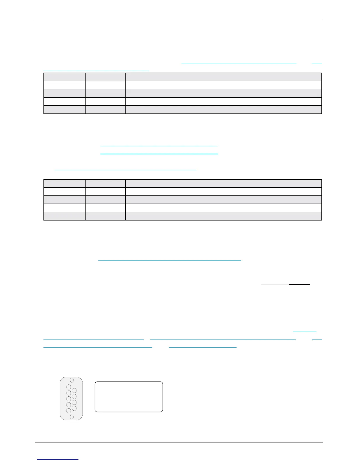
1
2
3
4
5
6
7
8
9
9 Pin D-SUB (female
connector) in cabinet front
seen from outside.
NMEA IN: Pin 1-2, RCV1 A, B
NMEA IN: Pin 6-7, RCV2 A, B
NMEA OUT: Pin 4-5, XMT1 A, B
NMEA OUT: Pin 8-9, XMT2 A, B
• COM 1: Pin 1-2 (RCV1 A, B), Pin 4-5 (XMT1 A, B) and 8-9 (XMT2 A, B)
• COM 2: Pin 6-7 (RCV2 A, B)
Fig. 4.9. NMEA connector XJ303.