49
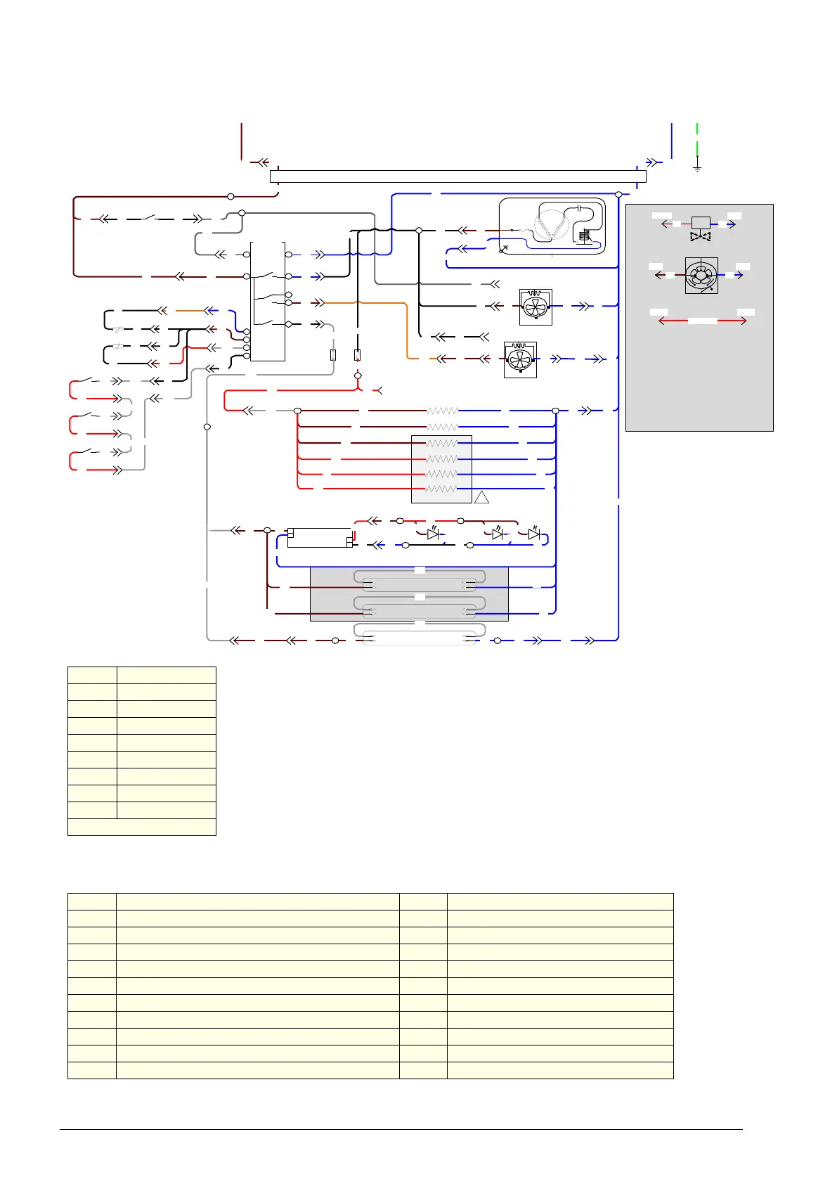
SKOPE TME/SKT ActiveCore
Wiring
Service Manual
Model: TME1500 Series and SKT1500 Series
Legend
S1/P1 IEC cabinet socket/plug S11/P11 Cabinet to sign intermediary socket/plug
S2/P2 Unit junction box to controller power socket/plug 1 (red 4-way) S12/P12 Cabinet sensor socket/plug (blue 2-way)
S3/P3 Unit junction box to controller power socket/plug (blue 4-way) S13/P13 Evaporator sensor socket/plug (black 2-way)
S4/P4 Unit junction box to controller signal socket/plug (6-way) S14/P14 Door sensor socket/plug (white 2-way)
S5/P5 Compressor unit socket/plug (blue 4-way) S15/P15 Pressure switch socket/plug (red 2-way)
S6/P6 Condenser motor unit socket/plug (red 4-way) T1 Unit terminals
S7/P7 Evaporator motor unit socket/plug (white 4-way) T2 Cabinet terminal block 1
S8/P8 Evaporator motor changeover socket/plug (white 4-way) T3 Cabinet terminal block 2
S9/P9 Light unit socket/plug (yellow 4-way) T4 Cabinet terminal block 3
S10/P10 Light unit socket/plug 2 (yellow 4-way) T5 Sign terminal block
<< Plug and socket O Terminal on terminal block
C
T1-5
S8-2 P8-2 P8-3 S8-3 P7-1 S7-1S7-2 P7-2
S5-1 P5-1
P2-1 S 2-1
P3-1 S 3-1
P3-2 S3-2
P3-4 S 3-4
6
7
4
5
2
Fan
3
1
Lights
8
9
10
11
Carel
Smart
Controller
Comp .
T1-1
BK
BN
BN
BU
BU
BN
BK
BK
OG
WH
Compressor
RS
C
L
N
Start
Relay
Compressor
Overload
T1-3
BK
S5-2 P5-2
BN
BU
BK
BN BU
S6-4 P6-4
S6-2 P6-2
P6-1 S6-1
GY
BK
Condenser Fan
BN BU
S8-1 P8-1
Evaporator Fan
BK
BU
BU
S7-4 P7-4
BU
BK
RD
T1-4
BN
S10-4
RD
RD
WH
WH
S9-2 P9-2
BN
BU
S4-1 P4-1
S4-2 P4-2
S4-3 P4-3
S4-4 P4-4
S12-1 P12-1
RD
BK
BK
OG
BK
WH
BK
BK
BK
BK
WH
WH
WH
RD
Door
Switch
S12-2 P12-2
S13-1 P13-1
S13-2 P13-2
S14-1 P14-1
S14-2 P14-2
Cabinet
Probe
E
L
N
S1-L P1-L P 1 -N S 1-N
BN BU
T1-2
GNYE
E
EMC Filter
BU
BN
S15-1 P15-1
P15-2 S15-2
Pressure Switch
S2-2 P2-2
S2-4 P2-4
BK
BU
T1-5
BN
GY
GY
BU
BU
BN
BU
WH
BK
WH
BK
FuseFuse
S9-4 P9-4
T2-2
& 3
BN
BU
T2-4/
5 & 6
BU
P9-1 S9-1
BN
WH
WH
RD
Door Switch
WH
BN
BU
LED Power
Supply
N
L
+
-
T3-1
RD
T3-2
BK
BN
BU
BN
BU
BN
BU
Side lights and pillar light
or shelf lighting
Pillar elements
WH
RD
Door Switch WH
BU
T4-2
T4-1
BK
S11-L P11-L
BN
S10-2 P10-2 P10-1 S10-1
BU
P11-N S 11-N
BN BU
Sign Light
WH
T5-1
T5-2
BN
BU
RD
T2-1
S16-2 P16-2
BN
S16-1 P16-1
BU
Side Light
WH
Side Light
WH
BN
BN
BU
BU
Shaded area is only
present in cabinets with T 8
LED Side Lights. For these
ca bin ets , the sid e or sh elf
lit LED strips are removed
Door element
Perimeter element
BU
BU
Solenoid Valve
M
BUBN
BUBN
Recirculation Fan
P5-2
P6-2
P5-1
P6-1
Note:
For cabinets with
remote units replace
compre ssor with
solenoid valve and
replace condenser fan
with recirculation fan
Fo r a re m ote unit the
pressure switch will also
be removed . A link wire
will replace it
P15-1
P15-2
RD - LINK
Link Wire
Door and Perimeter
elements are only
present on the tropical
cabinets (in shaded area )
RD
BN
Door element
Door element
BU
BU
RD
RD
Wire colours
BK Black
BN Brown
RD Red
OG Orange
GN Green
BU Blue
GY Grey
WH White
GNYE Green-Yellow
Based upon IEC 757 Standard