5 PICOSCALE HARDWARE
Table 5.7: Main performance data of DAC1
Parameter Typical Value Unit
Full-scale output voltage ±10 V
Sample-rate 10 MS /s
Resolution 12 Bit
Bandwidth f
1dB
2-2.5 MHz
Table 5.8: Main performance data of DAC2-5
Parameter Typical Value Unit
Full-scale output voltage ±10 V
Sample-rate 200 kS /s
Resolution 16 Bit
Bandwidth f
1dB
130-170 kHz
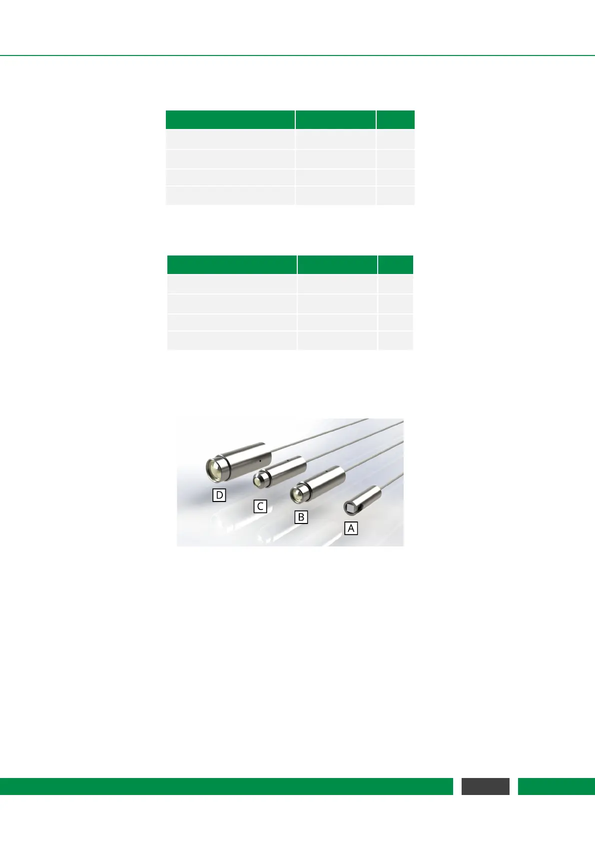
5.4 Sensor heads
Figure 5.8: Selection of PICOSCALE sensor heads: (A) PS-SH-C01, (B) PS-SH-F01, (C) PS-SH-C03, (D)
PS-SH-C02.
The PICOSCALE interferometer sensor heads are based on an optical fiber, a fiber ferrule, a colli-
mator and a beam splitter cube. The optical fiber (single mode, minimum bending radius 10 mm)
is terminated with a 8
◦
ferrule. The angle is introduced to suppress parasitic interferences. A gra-
dient index (GRIN) lens (also with 8
◦
angle) is glued to the ferrule and used to collimate the laser
beam. The key component is the beam splitter cube. The beam is split into two parts. One part is
guided to the reference mirror that is coated to one of the surfaces of the cube. The other part is
guided to the target. Given proper alignment, the probe beam interferes with the reference beam
in the beam splitter cube. The interfering light is guided through the optical fiber back into the
PICOSCALE Controller, where it is detected by a photo detector and the interference pattern is
evaluated.
40
PicoScale User Manual