7 PICOSCALE CONTROL GUI
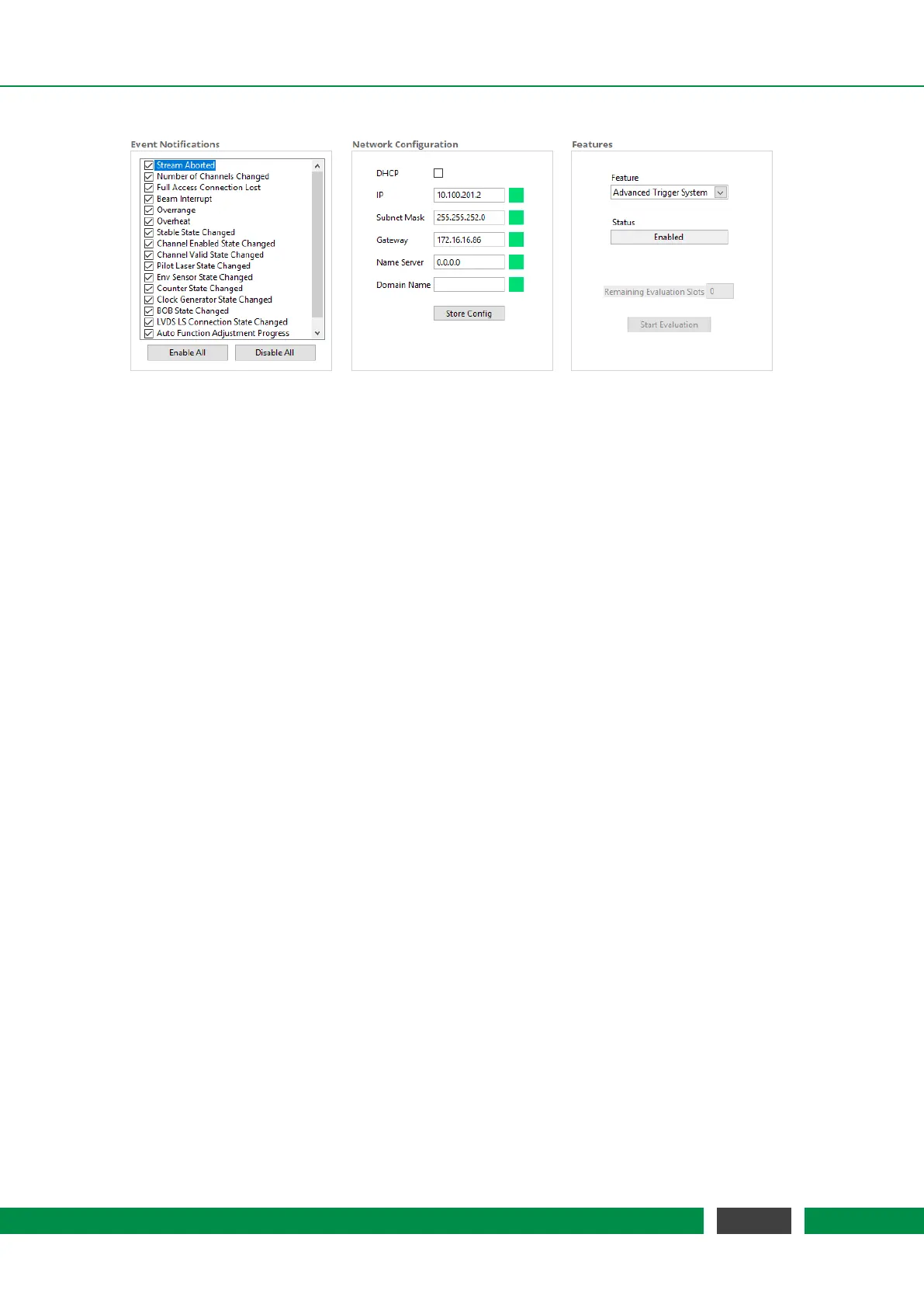
Figure 7.3: General Settings: (left) Configuration menu for Event Notification. (center) Network Con-
figuration. (right) Features Configuration.
You may activate the Dynamic Host Configuration Protocol (DHCP) if your server supports au-
tomatic assignment of IP addresses. If activated, the other fields are deactivated and have no
meaning. If DHCP is deactivated, a static IP Address, as well as other Ethernet properties like Sub-
net Mask, Gateway, Name Server and Domain Name can be configured in the appropriate panels.
Once all properties are defined, the configuration can be transmitted to the system by clicking on
the Store Config button. During transmission, the PICOSCALE checks the entered values, and if all
values are valid (indicated by the green LEDs), the desired configuration is activated.
The
PICOSCALE offers chargeable firmware upgrades, such as the Advanced Trigger System, the
Signal Generators and the Calculation System. In the Features menu at the right hand side of figure
7.3, the available features are displayed in the Feature drop-down menu.
All chargeable features can be evaluated for a certain time. Generally, 10 time slots are available
and can be activated individually. Each time slot allows to evaluate the selected feature for 8
hours. The remaining evaluation time slots are displayed in the Remaining Evaluation Slots fields.
By clicking the Start Evaluation button, a new time slot is started.
If you decide to upgrade your system with the feature, please contact SmarAct. You will receive a
firmware upgrade and the feature time is set to infinity automatically.
7.1.3 Status
The PicoScale status is located in the lower left part of the GUI and displays the current status of the
system. The red box (4) in figure 7.1 illustrates the location. The active channels are marked with
a green rectangle. The value Dead Path besides the active channels is calculated during the ad-
justment process and indicates the absolute distance between the measurement head and object
mirror.
The working range of the system is displayed below the channel indicator. If the target leaves
this range a new adjustment might be necessary. The Filter Rate describes a low pass filter that is
applied to position and ADC data and can be adjusted with the drop-down list. It can be switched
to the corresponding Cut-off Frequency using the button on the right side. The filter is implemented
in the FPGA and determines the system bandwidth.
51
PicoScale User Manual