7 PICOSCALE CONTROL GUI
7.3 Advanced Trigger
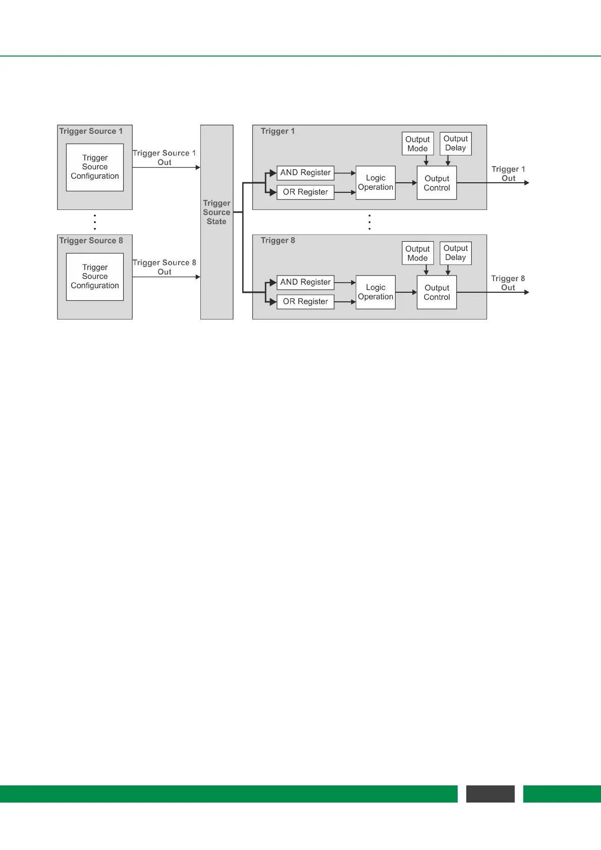
Figure 7.7: Block Diagram of the PICOSCALE Trigger System.
The Advanced Trigger System can be purchased as an additional feature for the PICOSCALE system
which allows to synchronize internal and external processes. Figure 7.7 shows the block diagram
of the Advanced Trigger System. The system offers eight trigger sources (left side) which can be log-
ically combined to up to eight actual trigger output signals (right side). These signals may be used
by other internal sub systems or can be output by the GPIO interface to control and/or synchronize
external devices.
Each individual trigger source has an output signal, which can be logically HIGH or LOW. All trigger
source signals are stored in a trigger source state register to which all eight triggers have access.
Each trigger can combine several trigger sources by logical operations (AND, OR, etc.) which allows
to define very complex trigger logics. Additionally, the trigger signal can be delayed or debounced
to produce stable and reliable output signals that can be logically HIGH or LOW. The following sub
systems can use trigger signals:
• Stream Generator, see section 7.6
– start / stop / pause the data stream
– define the rate at which the data frames are generated
• Digital IO Interface, see section 7.4.1
– output trigger signals as TTL or CMOS signals
• Clock Generators, see section 7.5.1
– start / stop a clock generator
• Counters, see section 7.5.4
– start / stop / increment a counter
The advanced trigger system can be configured in the Advanced Trigger System panel of the
PICO-
SCALE
Control GUI.
55
PicoScale User Manual