7 PICOSCALE CONTROL GUI
7.4 Interfaces
The Interfaces panel allows to configure the GPIO interface of the
PICOSCALE system. It groups
the Digital IO, AquadB and the Digital-to-Analog (DAC) sub-panels.
7.4.1 Digital IO interface configuration
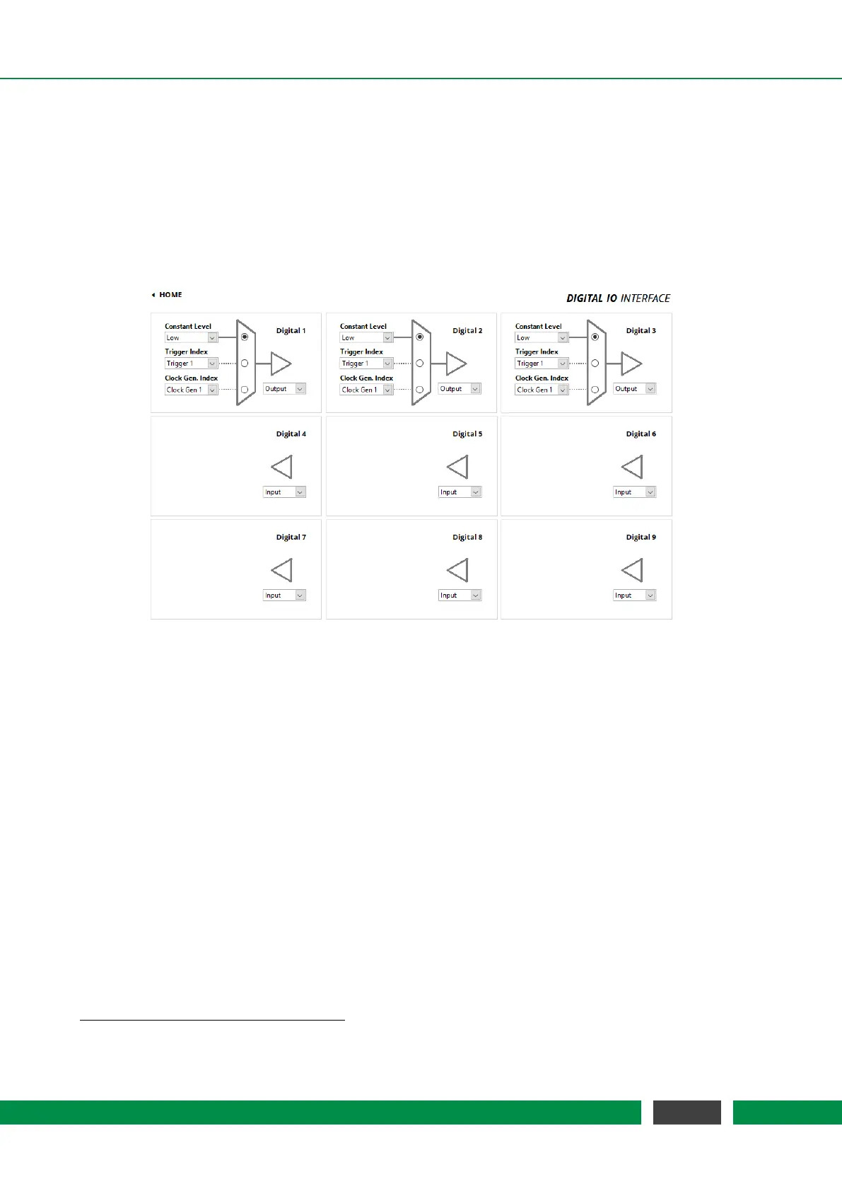
Figure 7.13: Configuration Menu of the Digital IO Interface.
The PICOSCALE offers nine digital IO pins, which are directly connected to the FPGA controller.
The IO pins Digital 1 to Digital 4 are TTL ports and Digital 5 to Digital 9 are CMOS ports. They have a
voltage range of 0 to 3.3 V
1
. Each pin can be configured as input or as output pin and is accessible
via the D-Sub 44HD connector at the system back side or more conveniently via the Breakout-Box
(BOB). When the Digital 1 to Digital 4 pins are accessed via the Breakout-Box (BOB), their voltage
range is raised to 0 to 5V.
Figure 7.13 shows the Digital IO Interface Configuration panel. Each pin can be configured individu-
ally. Digital 1 to Digital 3 are configured as Output ports, Digital 4 to Digital 9 are Input ports in this
figure.
The arrangement of the individual menus is equal to the pin arrangement of the
PICOSCALE
Breakout-Box. Each pin configuration has a drop-down menu in the bottom right corner, with
which the direction of the corresponding pin can be configured. The triangle in front of each LED
indicates whether the pin is configured as input or output.
On the left hand side of each panel three drop-down menus are available:
• Constant Level The output can be set to either logically HIGH or LOW.
1
In
PICOSCALE Controllers with the product codes PSC-CTRL-V1.0-TAB and PSC-CTRL-V1.1-TAB the signals GPIO.TTL*
have a 5V TTL level
63
PicoScale User Manual