7 PICOSCALE CONTROL GUI
Input
Immediate No Reset
Immediate Reset
(a)
Delayed No Reset
Delayed Reset
(b)
10
10
10
10
10
10
10
10
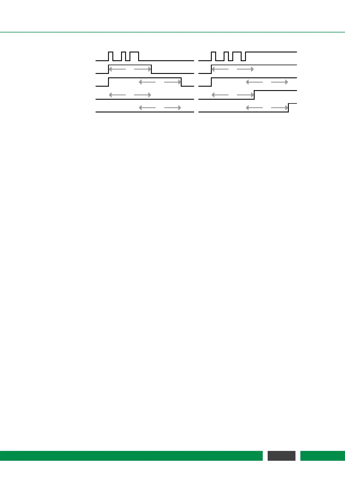
Figure 7.12: Trigger Output Control Behavior (output delay = 10). The input traces are the result
of the configured logic operation of the trigger and the eight traces below show the
resulting trigger signal for the four output modes. The first input trace (a) shows some
short pulses (e.g. a steady low level with some noise) while the second trace (b) shows
a noisy transition of the input signal from low to high (similar to a trace of a mechanical
button when pressed).
In the middle of figure 7.11 the Active Trigger Configuration table provides an overview of the con-
figured triggers. In this table the first column displays the name of the active triggers. The next
two columns show the state of the eight AND and OR masks. The last three columns display the
chosen logic Operation, the output Mode and the output Delay.
62
PicoScale User Manual