6 SETUP AND INSTALLATION
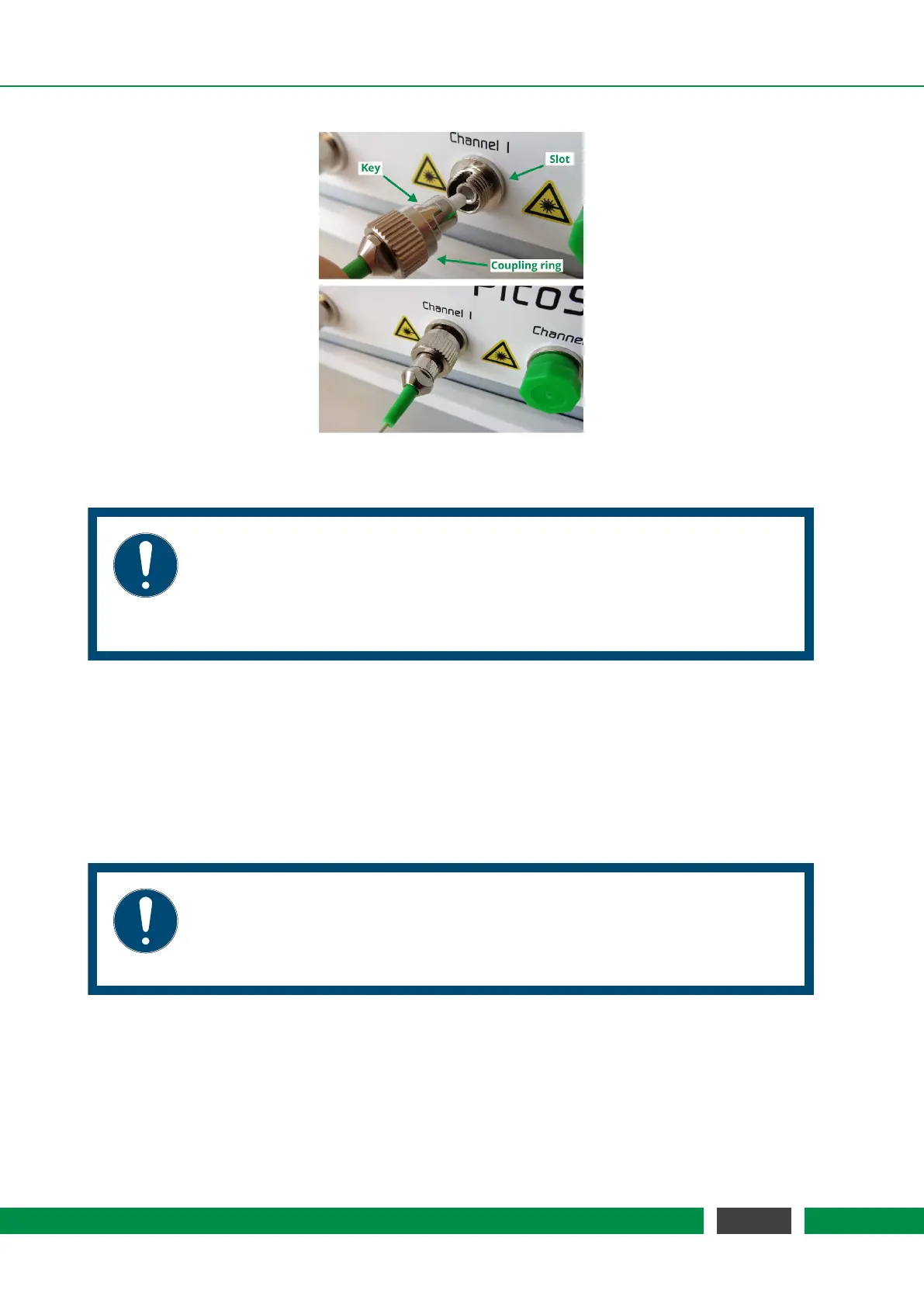
Figure 6.2: Connection of sensor head.
NOTICE
The PICOSCALE fiber network consists of FC/APC connectors. Do not plug any
other optical connector types to the system or its subcomponents. This may
cause significant damage to the optical system and dramatically drops the sys-
tem performance.
If purchased, connect the environmental module to the system front panel (figure 5.2, No. 1). A
red line and dot printed to the plug and connector mark the correct orientation. Place the sensor
as close as possible to the measurement head(s), to ensure that the sensor measures the local
environmental parameters, thus, reducing compensation errors.
The Breakout-Box (BOB) is connected using the included cable to the back panel of the PICO-
SCALE
housing. Although the Breakout-Box is hot pluggable, it is recommended to connect BOB
before the system is switched on.
NOTICE
The included BOB cable is quite sensitive to bending, thus respect a minimum
bending radius of 50 mm. Please handle the large cable connectors with care
and ensure that no pins are bent prior plugging.
6.4 System power up
Connect the power cable and press the main power switch on the back side (figure 5.2, No. 1). Now
the standby LED at the front panel should be on, indicating an active power connection (figure 5.2,
45
PicoScale User Manual