5 PICOSCALE HARDWARE
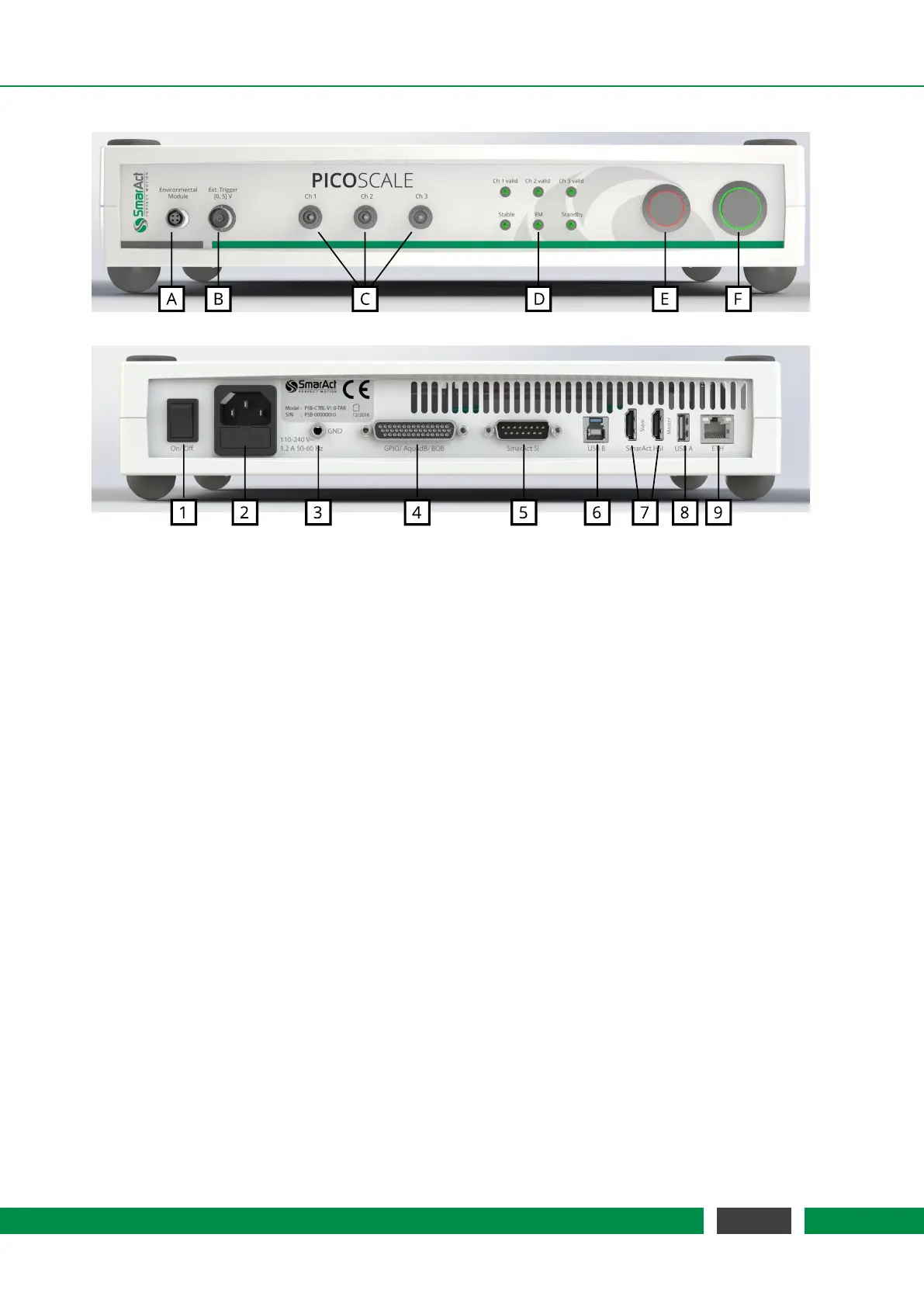
Figure 5.2: (top) Front side of the PICOSCALE Controller with different connectors for the (A) envi-
ronmental module, (B) external trigger connector, (C) sensor heads, (D) status LEDs, (E)
pilot laser and (F) power button. (bottom) Back side of the PICOSCALE Controller with
the (1) main power switch, (2) power connector (fuse included), (3) ground connector,
(4) GPIO and AquadB connector, (5) SmarAct sensor interface, (6) USB slave interface,
(7) SmarAct high-speed sensor interface, (8) USB master interfaces and (9) Ethernet
connector.
Figure 5.2 shows the front and back side of the PICOSCALE Controller. The front side exhibits
inputs for the environmental module (A), external trigger signals (B) and up to three measurement
heads (C). The environmental sensor is connected to the
PICOSCALE simply by plugging the mod-
ule connector into the connector at the
PICOSCALE housing. Red marks on the connector and
socket indicate the correct orientation.
The external trigger input is a BNC connector with an input range of [0,5] V. Internally, this trigger
input has a pull-up resistor (10 kΩ). Thus, the external trigger is always logically high when nothing
is connected to the input.
The optical inputs/outputs for up to three measurement heads are FC/APC connectors. It is impor-
tant, that only FC/APC connectors are used. Since these connectors have an 8
◦
-angled end face,
the orientation is crucial. Thus, the male connectors have keys, while the receptacles have corre-
sponding slots. It is mandatory to clean both, male and female connectors, with an appropriate
fiber cleaner (see chapter 6.3 for further information).
The status LED panel (D) offers a convenient overview of the system state. At the top, three LEDs
indicate the channel valid status. A channel becomes valid after the PICOSCALE sensor head
adjustment and the corresponding automated optimization routines have been successful. At the
bottom, the first LED indicates if the system is stable, which means that the wavelength of the
laser is actively stabilized. The
PICOSCALE is ready for a measurement, if the desired channels
are valid and the system is stable. The next LED marks, if an active connection to an environmental
30
PicoScale User Manual