5 PICOSCALE HARDWARE
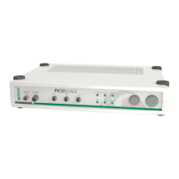
Figure 5.9: Setup of a PICOSCALE sensor head.
The open port of the beam splitter cube is the SmarAlign window. In specific sensor heads (for
example sensor head type C01) it can be used as a monitor to superimpose the beams reflected
from the reference and target mirror, respectively, using the visible pilot laser beam that is dif-
fusely scattered at this surface. All standard components are mounted in a titanium sleeve.
5.5 Environmental Module
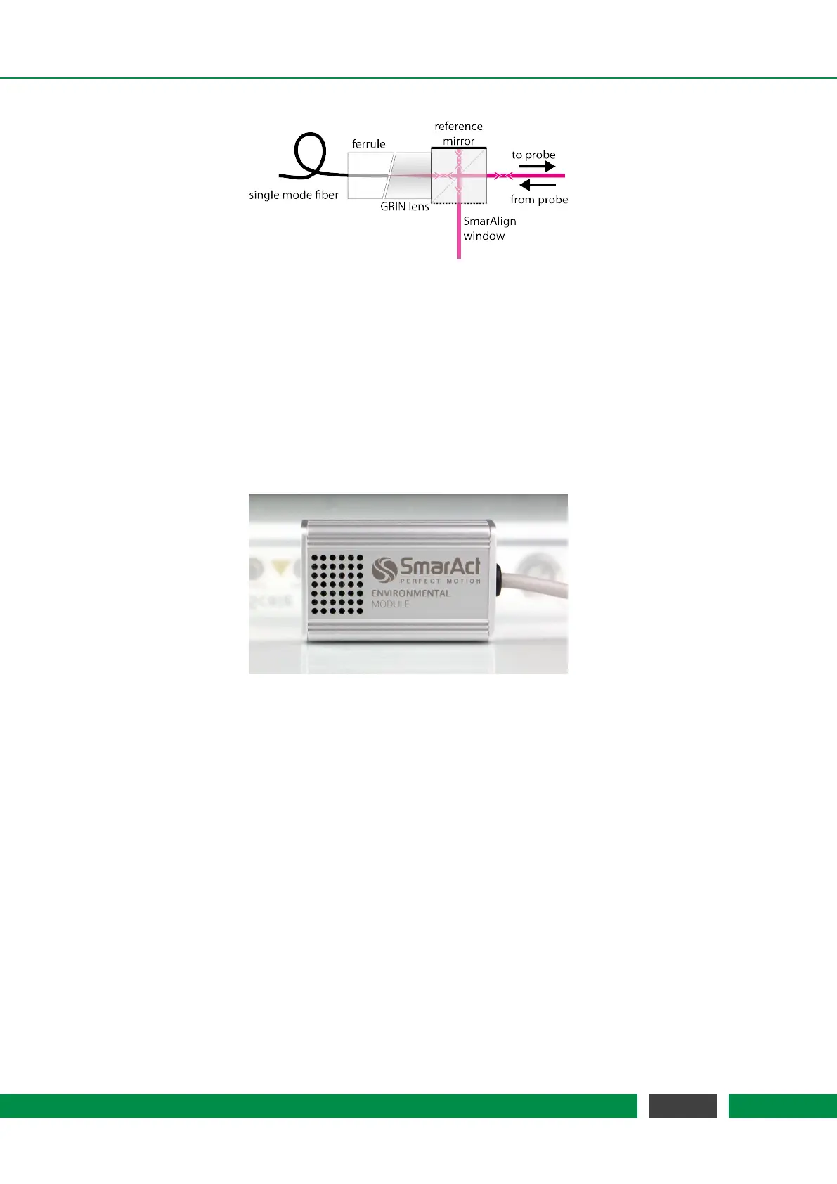
Figure 5.10: Environmental Module
To measure the environmental parameters (temperature, pressure, humidity), an environmental
module can be connected to the PICOSCALE Controller. Since the measurement of the environ-
mental conditions is most meaningful close to the sensor head, the environmental module has a
small chassis to make it possible to place it in close vicinity of the heads. The environmental mod-
ule is contained in an aluminum housing as small as 32x50x16 mm³. A microprocessor collects the
data of the individual sensors and sends them to the FPGA for further processing. The measure-
ment bandwidth is 1 Hz which is sufficient to detect variations in the environmental conditions.
The accuracy of the environmental module is:
• temperature: ± 200 mK
• pressure: ± 2 mbar
• relative humidity: ± 2%
These measurement uncertainties result in a position accuracy of typically <1 ppm.
41
PicoScale User Manual