7 PICOSCALE CONTROL GUI
7.5.2 Arbitrary Signal Generator
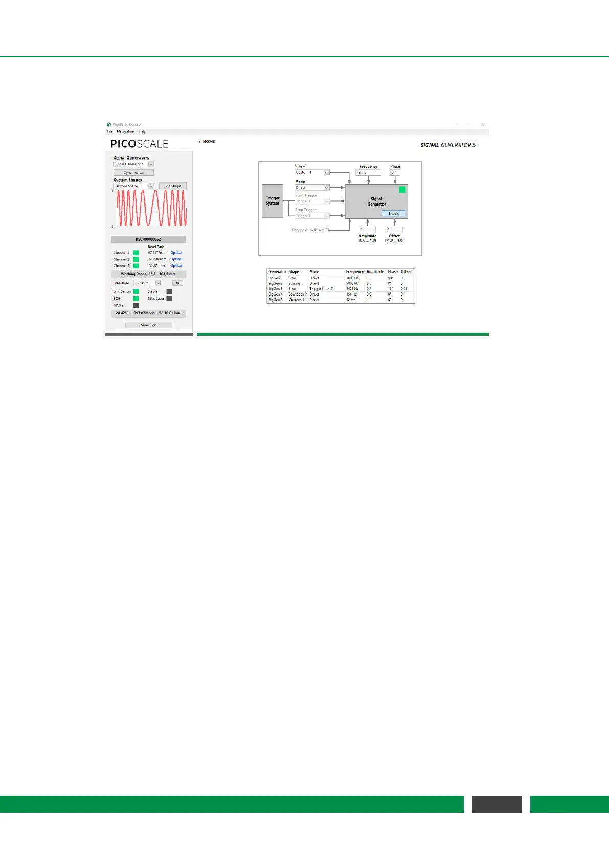
Figure 7.17: Configuration Menu of the Arbitrary Signal Generators. In this example a frequency
modulation was uploaded as customized signal shape.
The
PICOSCALE offers basic signal generator functionality with sine, square and sawtooth shapes.
Additionally, custom shapes can be uploaded as CSV files. In the configuration panel, see fig.
7.17, you can configure up to five signals (corresponding to five DAC interfaces). For each signal
generator you can choose sine, square, sawtooth (P: slow positive ramp, N: slow negative ramp)
or custom shapes in the Shape drop-down menu.
The frequency of the signals can be chosen between 1 mHz and 2.5 MHz. Note, that only DAC1
has a high 10 MHz sample rate and may be used to output fast signals. DAC2–DAC5 are limited to
200 kHz sample rate. The amplitude can be set in a range between 0 and 1 and the offset of the
signal can individually be set in a range between -1 and 1, where -1 corresponds to −10 V and 1
to 10 V. For example, a square signal with values between 0 and 5 Volt (i.e. TTL standard) can be
generated with the setting: shape Square, amplitude 0.25, offset 0.25.
When more than one signal generator is used, the signals can be synchronized with each other by
clicking the Synchronize button in the upper left part of the Signal Generator panel.
In the Custom Shapes panel, up to five custom shapes can be uploaded from CSV files. The files
must consist of 2
12
=4096 float numbers (double, 64 bit) which represent the amplitude of the
signal at each point. Thus the numbers have to be in the range [-1,1]. (Decimal sign is "." and
the individual entries have to be separated by a line break.) The shape of the uploaded signal
is displayed in the graph. The Edit Shape button opens the Custom Shape Editor which allows to
define a custom signal shape by entering a formula or by uploading it from a CSV file.
68
PicoScale User Manual