5 PICOSCALE HARDWARE
5.2.2 Optical outputs
CAUTION
Laser outputs. The
PICOSCALE Controller contains an infrared diode laser with
an output of less than 0.2 mW at 1520 nm - 1580 nm and a red diode laser with
an output power of less than 0.6 mW at 650 nm. Do not stare into the beam and
ensure the laser light is always appropriately guided.
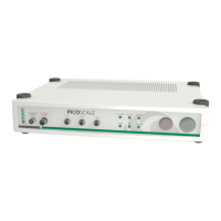
The PICOSCALE Controller has three optical outputs at the front panel of the chassis. Directly
after start up, the infrared measurement laser is enabled. This laser source has an output power
of maximum 0.2 mW per channel at a wavelength of 1520 nm - 1580 nm.
To improve the adjustment of the interferometer heads the
PICOSCALE Controller provides the
possibility to switch on a red pilot laser with the pilot laser button on the front panel. The pilot
laser has a output power of max. 0.6 mW per channel at a wavelength of 650 nm. It has no
influence on the measurement of the PICOSCALE Controller.
5.2.3 Power connection
Connect the
PICOSCALE Controller only with the provided IEC power cord and properly estab-
lished protective earth. After connecting the power cord use the main power switch to set the
system into standby mode. Finally press the power button on the front panel to start the system.
Change the main fuse
The PICOSCALE Controller is protected with a 2.5 A glass tube fuse with a slow blow timing be-
haviour. To prevent permanent damage or fire, the fuse must only be replaced with an equivalent
fuse if required (e.g. ESKA No. 522.500). The dimension of the glass tube is 20 x 5 mm.
WARNING
To prevent electrical shock, remove the power cord from the
PICOSCALE Con-
troller before replacing the fuse.
To change the fuse, remove the power cord and open the fuse holder (see figure 5.2). There are
slots for two fuses. The first slot contains the active fuse, in the second slot a fuse for replacement
is included. Remove the damaged fuse and replace it with a slow blow 2.5 A glass tube fuse with
the dimension of 20 x 5 mm.
32
PicoScale User Manual