5 PICOSCALE HARDWARE
5.3.1 Differential Digital Interface DDI
The Differential Digital Interface (DDI) provides two differential digital signals, which can be used
for different digital protocols, e.g. AquadB and Serial Data. With the Breakout-Box the signals are
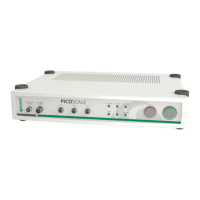
distributed to three DSub 15 connectors, one per channel. The pin assignment is shown in figure
5.4 and specified in table 5.1.
Figure 5.4: Pin assignment of the DSub 15 connector.
Table 5.1 – Pin assignment of DSub 15 AquadB connectors
Signal Direction AquadB serial data
1 Out A positive CLOCK positive
2 Out B positive DATA positive
3 - 7 - not connected -
8 - System Ground System Ground
9 Out A negative CLOCK negative
10 Out B negative DATA negative
11 - 15 - not connected -
Shielding - System Ground System Ground
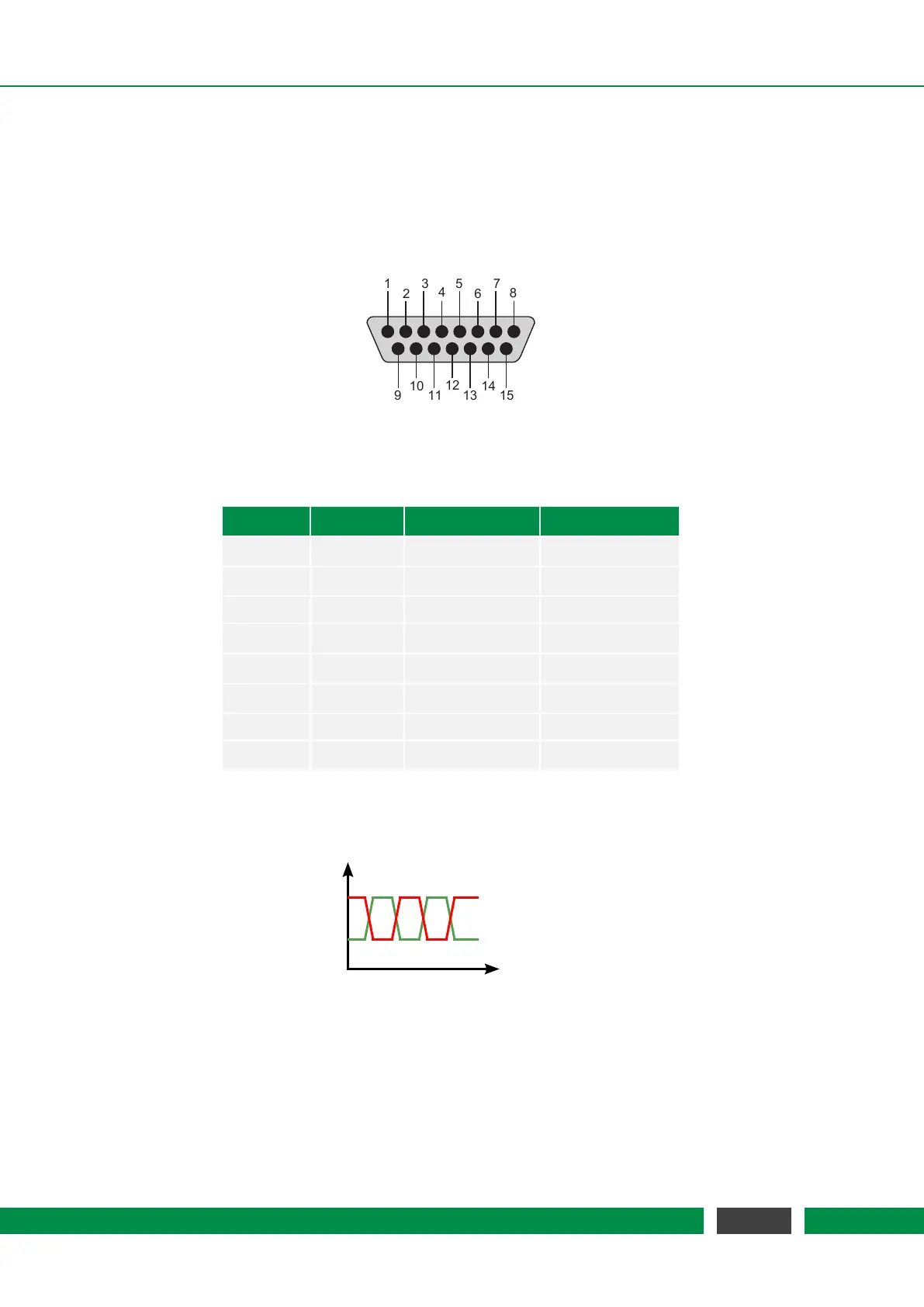
The output levels of the specific DDI pins are illustrated in figure 5.5. Main performance parame-
ters are listed in 5.2.
1
3.5
V
t
AquadB.X_P
AquadB.X_N
Figure 5.5: Output level of the specific pins of the AquadB connector, where the X is to be replaced
by the individual channel number and quadrature (A or B). The indices P and N denote
the positive and negative part of a differential AquadB pair.
36
PicoScale User Manual