5 PICOSCALE HARDWARE
Table 5.2: Main performance data DDI
Parameter Typical Value Unit Comment
V
O
Diff
0 - 5 V Differential output voltage
V
IH
Diff
0.2 V Differential high-level input voltage
V
IL
Diff
-0.2 V Differential low-level input voltage
f
max
5 MHz Max. frequency per differential pair
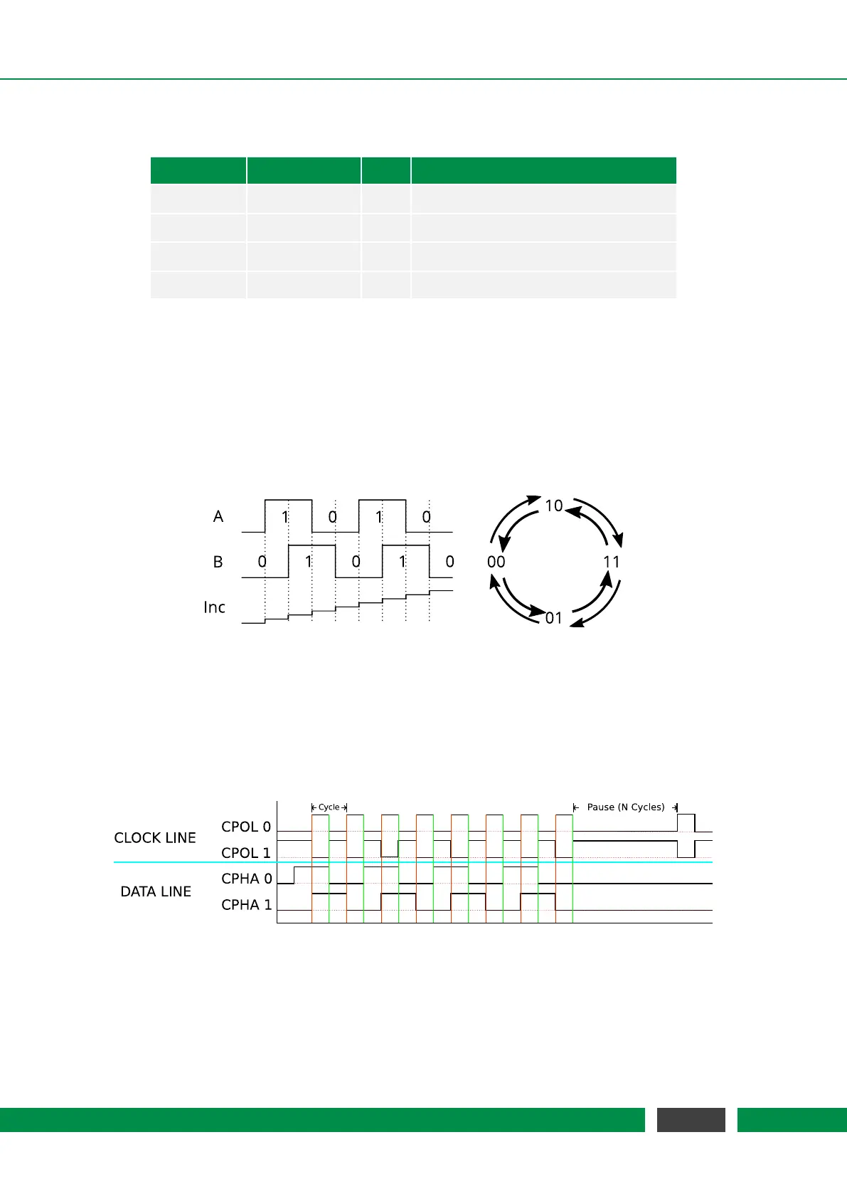
BOB AquadB
Industry standard AquadB receivers are often able to receive differential quadrature signals as
provided by the PICOSCALE Controller. In figure 5.6 the AquadB signals are shown schematically.
With the signals A and B four states can be encoded, each state indicates a position increment. So
the maximal increment frequency is 4 times the maximum differential pair frequency, in this case
20 MHz.
Figure 5.6: Scheme of the differential A and B signal and the according position increment of the
Quadrature interface.
The direction of the position change is given by the order of the cases.
BOB Serial Data
Figure 5.7: Clock and data cyles on the serial interface. The CLOCK LINE can either have a negative
zero level or a positive zero level. The DATA LINE can either be written with rising or the
falling edge of the clock.
Each of the three DSub 15 connectors can be configured to act as a serial data output. In figure
5.7 the options are illustrated. The upper part of the figure shows the options of the clock line and
37
PicoScale User Manual