7 PICOSCALE CONTROL GUI
Then you have to align sensor head and target mirror with respect to each other. To rate and
optimize the alignment, use the Lissajous graph and the signal quality bar.
NOTICE
The absolute number of the signal quality has no meaning. It is just a temporary
indicator which helps you to optimize the current alignment. It is dependent on
many factors so that it cannot be used for comparison with previous alignments
with slightly different settings (working range, different channels, etc.).
When the sensor head is tilted relative to the target mirror, the shape (diameter and thickness) of
the Lissajous figure as well as the signal quality change. However, during this alignment the signal
amplification is actively adjusted, so that the signal amplitudes cover the whole ADC range. A
very sensitive way to optimize the orientation of the measurement heads is to "freeze" the analog
gains, by pressing the Freeze Gains button. In this case, the diameter of the corresponding Lissajous
figure changes due to tilting of the sensor heads and should be maximized. (If, during this process,
the Lissajous figure size exceeds the display, simply "unfreeze" and freeze the gains again.)
After the manual adjustment is done, start the automatic adjustment by clicking the Start Auto Ad-
justment button. During this phase, the channel electronics (gains, demodulation phases, etc.), as
well as the internal signal processing algorithms are optimized automatically. A Progress bar indi-
cates the status of the auto adjustment. The Results panel summarizes the results of the individual
subroutines of the adjustment process. To guarantee optimal performance, the enabled channels
should be valid and the system must be stable. The adjustment process can be aborted at any
time, simply by deactivating the Manual Adjust or the Auto Adjust buttons.
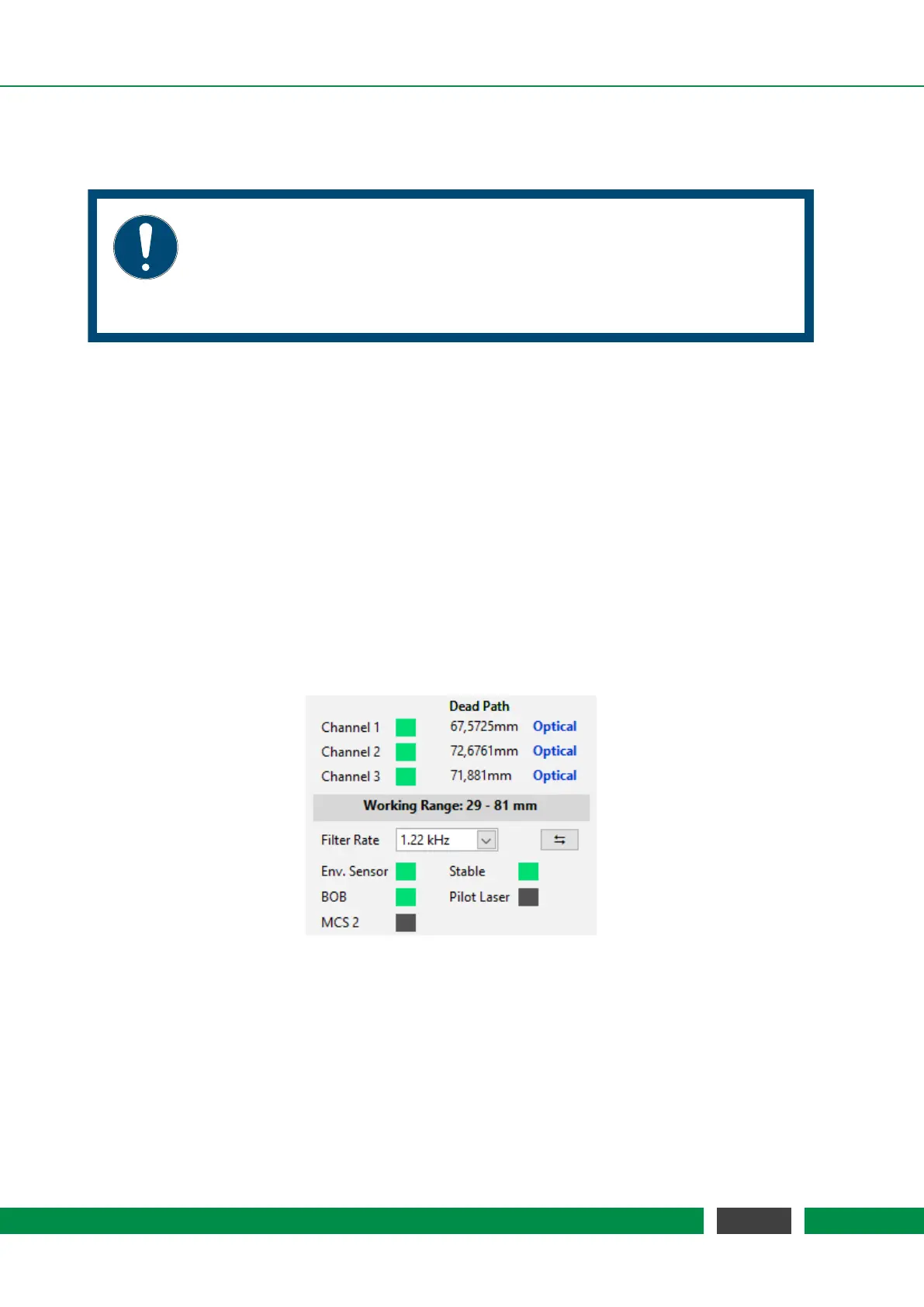
Figure 7.6: Results of the Auto Adjustment routine. All channels are valid and the laser is stable.
The label Optical indicated that optical pathlengths are measures, i.e. environmental
compensation is not active.
54
PicoScale User Manual