-15-
No.EX※※-OMS0027
SI Unit
Model Indication and How to Order
EX600- S EN 3
SI Unit
Output type / Number of ports
Symbol Content
Protocol
3 PNP (negative common) / 2 port
Symbol Content
4 NPN (positive common) / 2 port
EN EtherNet/IP
TM
Summary of Product parts
No. Description Function
1 Status display LED Displays the status of the unit.
2 Display cover
Open at the switch configuration.
3 Display cover tightening screw Loosen to open the display cover.
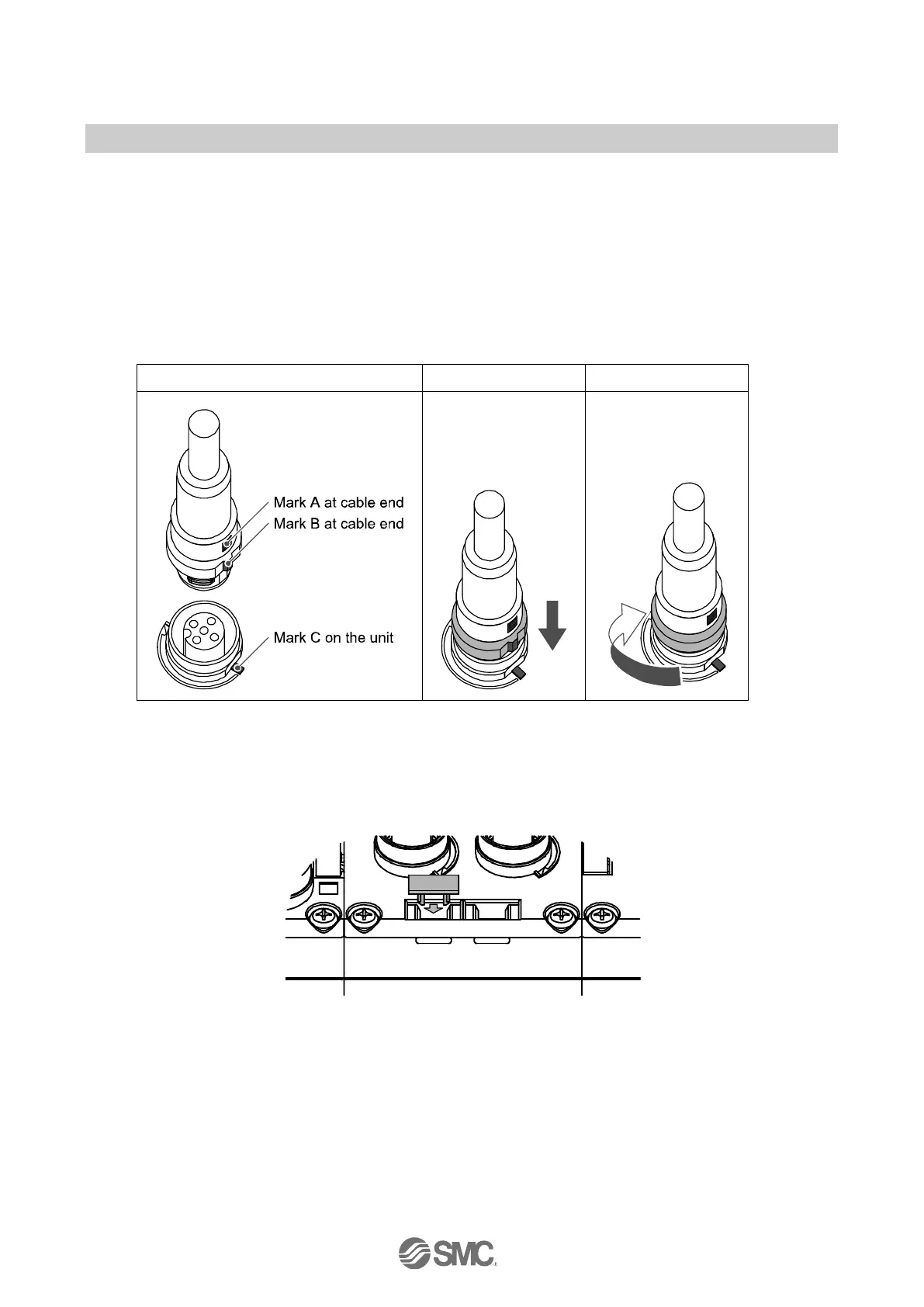
4 Connector (BUS OUT)
Connects the cable for fieldbus outputs.
(M12, 5 pin, socket: SPEEDCON)
5 Marker groove Groove to mount a marker.
6 Connector (PCI)
Connects the cable of the handheld terminal.
(M12, 5 pin, socket: SPEEDCON)
7 Valve plate mounting screw hole Fixes the valve plate.
8 Valve plate mounting groove Groove to insert the valve plate into.
9 Joint bracket Bracket for joining to adjacent units.
10 Unit connector (plug) Transmits signals and power supplies to adjacent units.
11 Connector (BUS IN)
Connects the cable for fieldbus inputs.
(M12, 5 pin, socket: SPEEDCON)
12 Seal cap (2 pcs.) Mounted on to unused connectors (BUS OUT and PCI).
 Loading...