-61-
No.EX※※-OMS0027
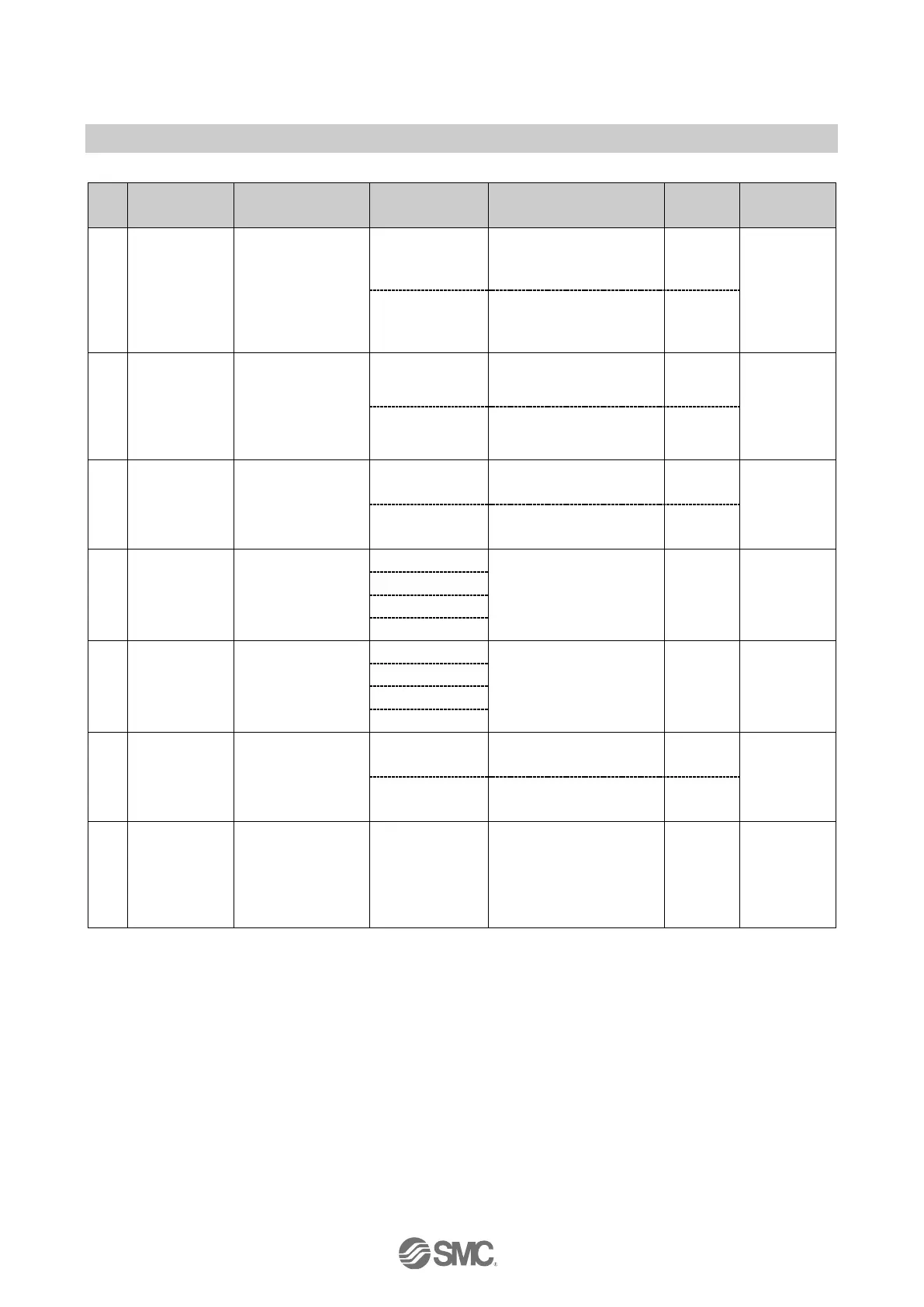
•When Diagnostic mode 1 and byte order of analogue value (LSB-MSB) are selected.
1
Input data Output data
Byte0 Diagnostic data byte0 DY□B (Unit 1) Output 0 to 7
Byte1 Diagnostic data byte1 DY□B (Unit 2) Output 0 to 7
Byte2 Diagnostic data byte2 Output 0 to 7
Byte3 Diagnostic data byte3 Output 8 to 15
Byte4
Lo byte
Output 16 to 23
Byte5
AXA channel 0
(Unit 0)
Hi byte
SEN3 (Unit 5)
Output 24 to 31
Byte6
Lo byte
Byte7
AXA channel 1
(Unit 0)
Hi byte
Byte8 DX□B (Unit 3) Input 0 to 7
Byte9 Input 0 to 7
Byte10
DX□D (Unit 4)
Input 8 to 15
Byte11 Padding data
Total 12 bytes
6 bytes
•When Diagnostic mode 1 and byte order of analogue value (MSB-LSB) are selected.
1
Input data Output data
Byte0 Diagnostic data byte0 DY□B (Unit 1) Output 0 to 7
Byte1 Diagnostic data byte1 DY□B (Unit 2) Output 0 to 7
Byte2 Diagnostic data byte2 Output 0 to 7
Byte3 Diagnostic data byte3 Output 8 to 15
Byte4
Hi byte
Output 16 to 23
Byte5
AXA channel 0
(Unit 0)
Lo byte
SEN3 (Unit 5)
Output 24 to 31
Byte6
Hi byte
Byte7
AXA channel 1
(Unit 0)
Lo byte
Byte8 DX□B (Unit 3) Input 0 to 7
Byte9 Input 0 to 7
Byte10
DX□D (Unit 4)
Input 8 to 15
Byte11 Padding data
Total 12 bytes
6 bytes
1: Refer to "Parameter Setting" (page 42) for setting the byte order of analogue value.
 Loading...