Figure 4: Power optimizer grounding terminal
5. Verifythateachpoweroptimizerissecurelyattachedtothesupportingstructureorthemodule.
6. Recordpoweroptimizerserialnumbersandlocations,asdescribedin"Step4:Reportingand
MonitoringInstallationData"onpage50
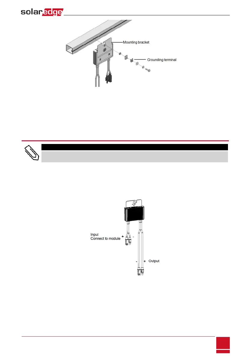
Step 2: Connecting a PV Module to a Power
Optimizer
NOTE
Images are for illustration purposes only. Refer to the label on the product to identify the plus and
minus input and output connectors.
Foreachofthepoweroptimizers:
l ConnectthePlus(+)outputconnectorofthemoduletothePlus(+)inputconnectorofthepower
optimizer.
l ConnecttheMinus(-)outputconnectorofthemoduletotheMinus(-)inputconnectorofthe
poweroptimizer.
Figure 5: Power optimizer connectors
Chapter 2: Installing the Power Optimizers
SolarEdge-StorEdge Installation Guide MAN-01-00262-1.3
17