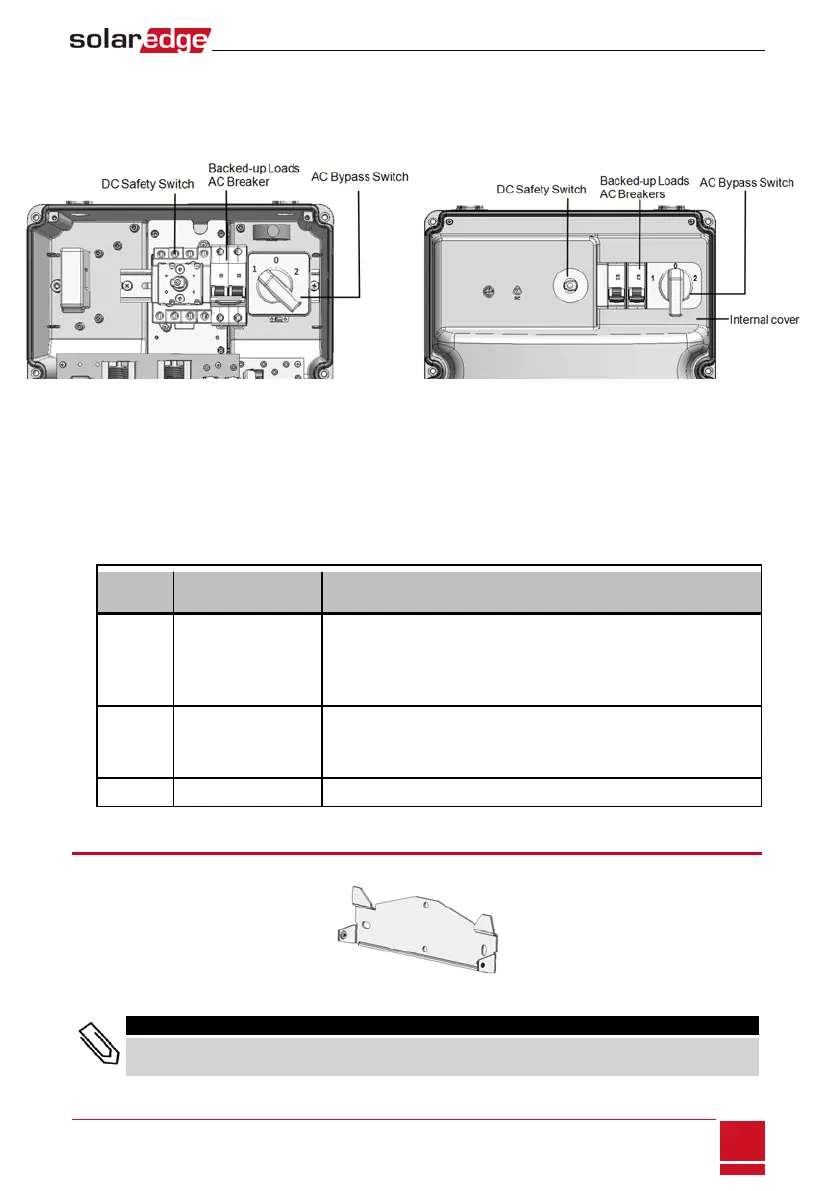
Internal AC Breaker and Bypass Switch
ThefollowingcomponentsarepartoftheConnectionUnitandmaybeaccessedfortroubleshootingor
maintenancebyremovingtheinternalcover.
Figure 10: Connection Unit with and without internal cover
l Backed-up Loads AC Breaker:MainACbreakerforthebacked-uploads.EnsurethisbreakerisUP
beforestartingupthesystem.
l AC Bypass Switch:Thisswitchbypassestheinverterfunctionalityincaseofinvertermalfunction.
Maintainingpowertothebacked-uploadsisenabledbyconnectingtheloadsdirectlytothegrid.
Therearethreeswitchpositions.Thefollowingtabledescribesthefunctionalityanduseofeach
position:
Switch
position
Use Case Functionality
1 (left)
(Default)
Normal operation
Normal operation.
The backed-up loads panel is connected through the software
controlled switches to the AC grid (during normal operation), or to the
inverter (via auto-transformer, for backup power).
2 (right) AC bypass
This mode disables the backup functionality.
The backed-up loads panel is connected directly to the AC grid through
the bypass switch. Use in case of inverter malfunction.
0 Not in use
Mounting the Inverter
Theinverterissuppliedwithamountingbracket.
Figure 11: Mounting bracket
NOTE
Make sure the mounting surface or structure can support the weight of the inverter and bracket, and
make sure that it spans the width of the bracket.
Chapter 3: Installing the Inverter
SolarEdge-StorEdge Installation Guide MAN-01-00262-1.3
23