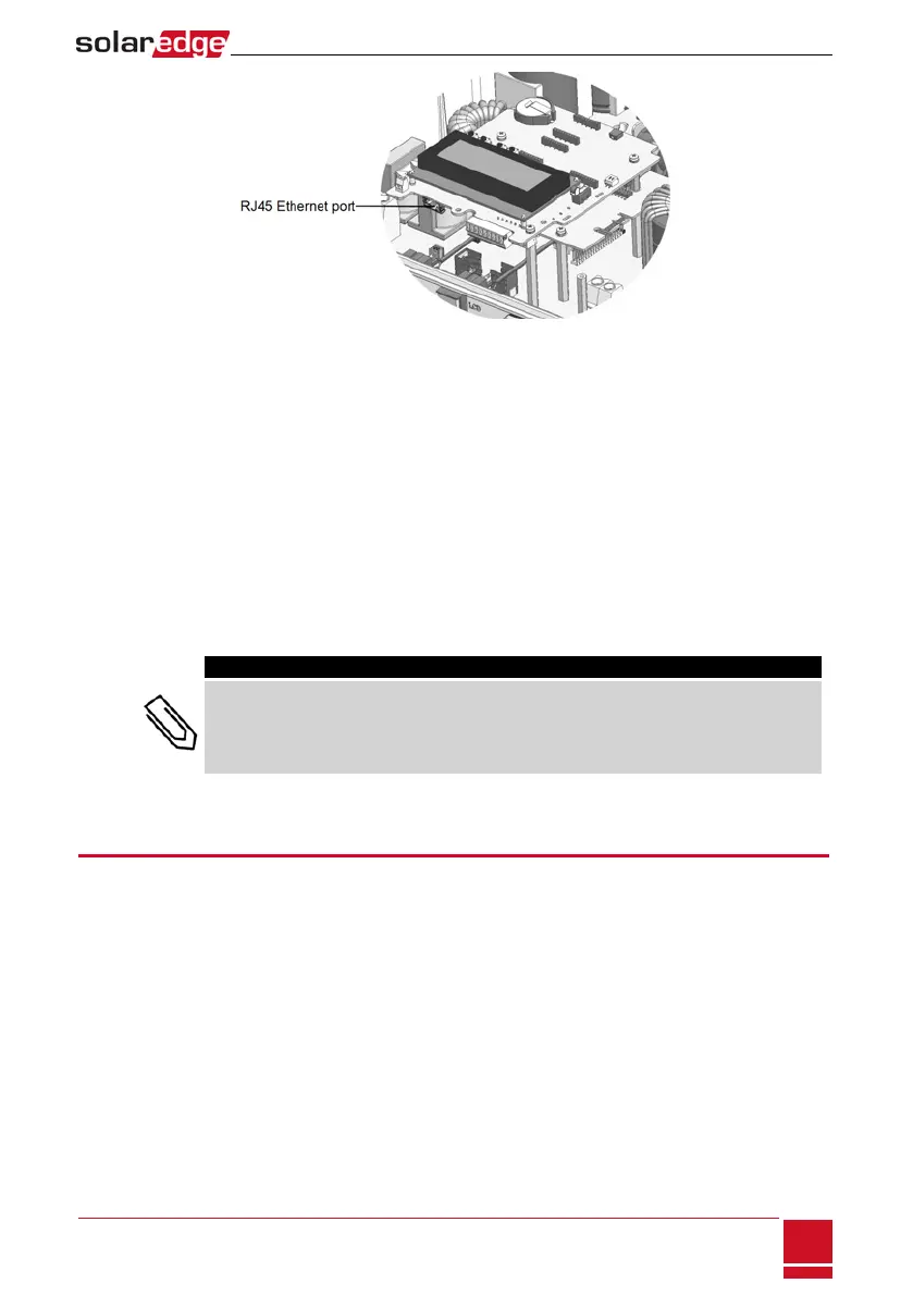
Figure 37: The RJ45 Ethernet connection
7. Fortheswitch/routerside,useapre-crimpedcableoruseacrimpertoprepareanRJ45
communicationconnector:InserttheeightwiresintotheRJ45connectorinthesameorderasabove
(Figure36).
8. ConnectthecableRJ45connectortotheRJ45portoftheEthernetswitchorrouter.
Youcanconnectmorethanoneinvertertothesameswitch/routerortodifferentswitches/routers,
asneeded.EachinvertersendsitsmonitoreddataindependentlytotheSolarEdgemonitoring
platform.
9.
TheinverterisconfiguredbydefaulttoLAN.Ifreconfigurationisrequired:
a. MakesuretheON/OFFswitchisOFF.
b. TurnONtheACtotheinverterbyturningONthecircuitbreakeronthemaindistributionpanel.
c. Usetheinternaluserbuttonstoconfiguretheconnection,asdescribedinCommunicationon
page60.
NOTE
If your network has a firewall, you may need to configure it to enable the connection to the
following address:
l Destination Address: prod.solaredge.com
l TCP Port: 22222, 22221, or 80 (for incoming and outgoing data)
10. Verifytheconnection,asdescribedinVerifyingtheConnectiononpage80.
Creating an RS485 Bus Connection
TheRS485optionenablescreatingabusofconnectedinverters,consistingofupto31slaveinvertersand
1masterinverter.Usingthisoption,invertersareconnectedtoeachotherinabus(chain),viatheir
RS485connectors.Thefirstandlastinvertersinthechainmustbeterminatedasdescribedonpage80.
RS485wiringspecifications:
l Cabletype:Min.3-wireshieldedtwistedpair(ashieldedEthernetcable(Cat5/5ESTP)maybeused)
l Wirecross-sectionarea:0.2-1mm²/24-18AWG(aCAT5cablemaybeused)
l Maximumnodes:32
l Maximumdistancebetweenfirstandlastdevices:1km/3300ft.
Chapter 9: Setting Up Communication to the Monitoring Platform
SolarEdge-StorEdge Installation Guide MAN-01-00262-1.3
77