NOTE
If using a cable longer than 10 m / 33 ft in areas where there is a risk of induced
voltage surges by lightning, it is recommend to use external surge protection
devices.
For details refer to: http://www.solaredge.us/files/pdfs/lightning_surge_
protection.pdf. A surge protection device is available from SolarEdge.
https://www.solaredge.com/sites/default/files/rs485_surge_protection_kit_
installation_guide.pdf
If not using surge protection, connect the grounding wire to the first inverter in the
RS485 chain; make sure the grounding wire is not in
contact with other wires. Connect the grounding wire to the grounding bus-bar in
the Connection Unit.
NOTE
An additional RS485 port (RS485-E) is available from SolarEdge, allowing
configuration of multiple RS485 buses for communications in large sites; Refer to
http://www.solaredge.us/files/pdfs/RS485_expansion_kit_installation_guide.pdf).
ThefollowingsectionsdescribehowtophysicallyconnecttheRS485busandhowtoconfigurethebus.
To connect the RS485 communication bus:
1. RemovetheinvertercoverasdescribedinRemovingtheInverterCoveronpage44.
2. Removethesealfromoneoftheopeningsincommunicationglandandinsertthewirethroughthe
opening.
3.
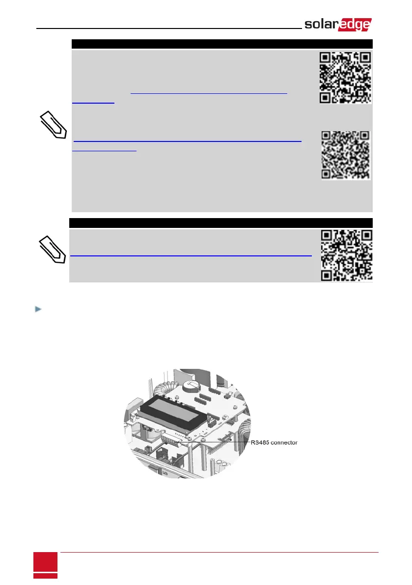
Pulloutthe9-pinRS485terminalblockconnector,asshownbelow:
Figure 38: The RS485 terminal block
SolarEdge-StorEdge Installation Guide MAN-01-00262-1.3
78
Creating an RS485 Bus Connection