4-42
BVW-55 P2
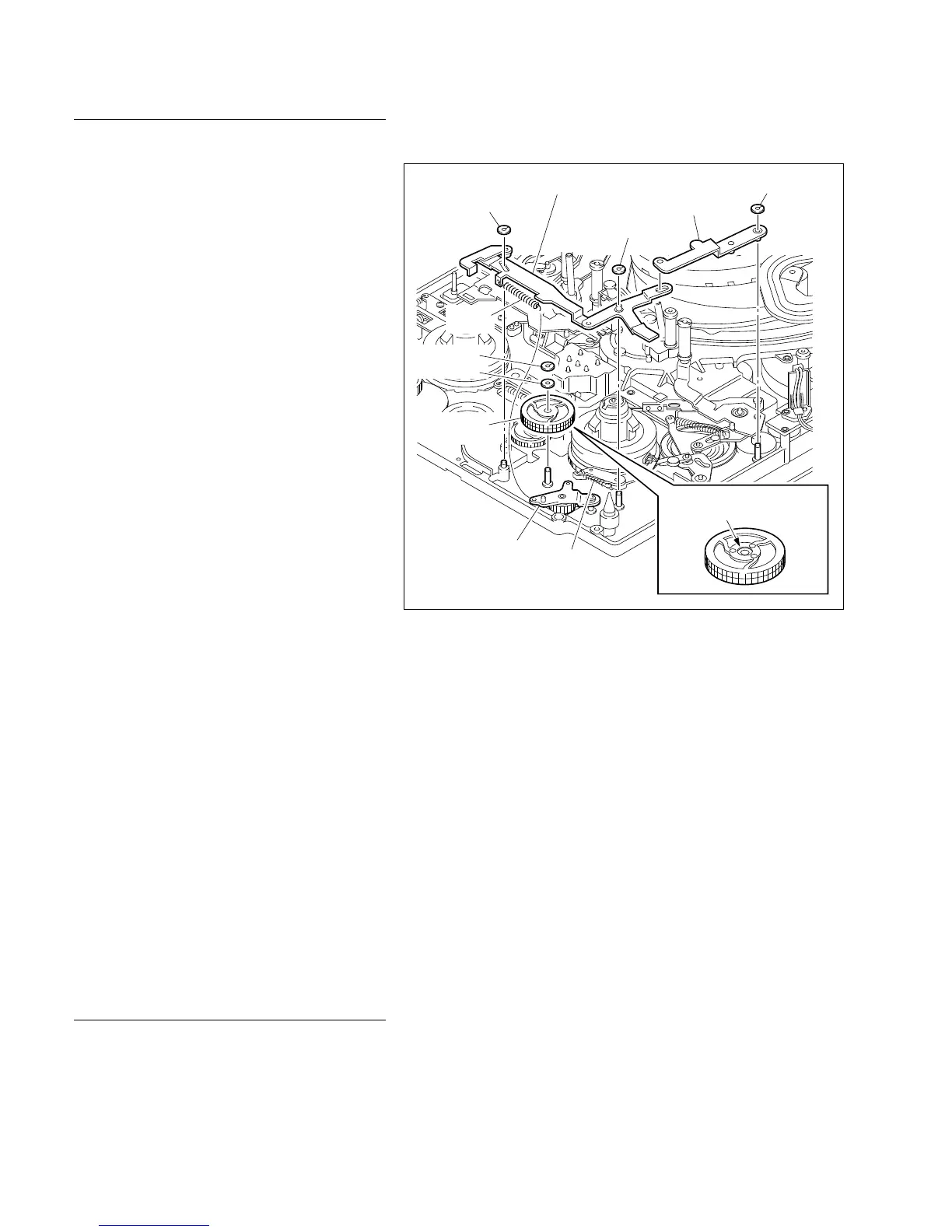
Stop washer
Polywasher
Stop Washer
Stop washer
Stop washer
Gear connecting
arm assembly
Eject link assembly
Release arm assembly
Spring
Spring
Install the T idler assembly
with the dented surface up.
Replacement
1. Spring removal
Unhook the two springs of the gear connecting
arm assembly side shown in the figure.
2. Eject link assembly/release arm
assembly removal
Remove the two stop washers fastening the eject
link assembly and one stop washer fastening the
release arm assembly using tweezers, then
remove the eject link and release arm assemblies
from the mechanical deck.
3. T idler assembly removal
Remove the stop washer using tweezers, then
remove the T idler assembly.
n
Do not remove the polywasher (0.25 thickness :
3-303-961-11) at the bottom of the T idler
assembly.
4. T idler assembly installation
(1) Clean the installation shaft with cleaning
cloth moistened with cleaning fluid.
(2) Apply a 1/4 drop of oil to the installation
shaft.
(3) Install a new T idler assembly in the shaft
with the dented surface shown in the figure
up.
(4) Install the polywasher (0.13 thickness : 3-
303-961-01).
(5) Install a new stop washer.
5. Eject link assembly/release arm
assembly installation
Install the eject link and release arm assemblies
using three new stop washers.
6. Spring installation
Hook the two springs removed in step 1 to the
gear connecting arm assembly.
Check after replacement
7. Operation check
Insert the cassette tape and check that the PLAY,
F-FWD, and REW operations are normal.
4-12. T Idler Assembly Replacement