5-25
BVW-55 P2
G
H
J
E
F
I
F
E
> 0.9
,
G
H
> 0.9
,
I
J
> 0.9
C
D
A
B
B
A
> 0.80
,
C
A
> 0.80
,
D
A
> 0.80
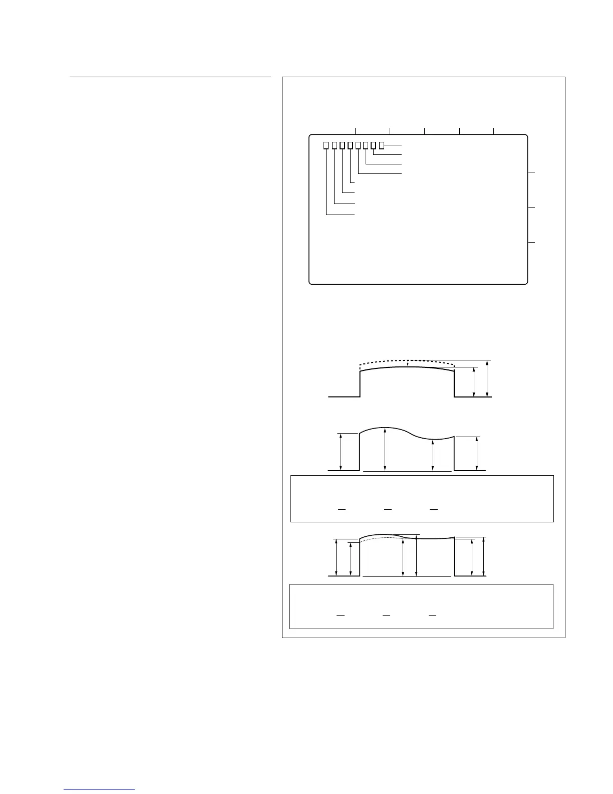
80 %
MAX
The output level of the waveform should be more than 80 %
of the maximum value.
Spec. 6:
The fluctuation value in each portion of a waveform should
be less than 10 %.
Spec. 7:
RF envelope waveform
. Connection of the oscilloscope
CH-1 : TP804 (Y RF)
TRIG : TP807 (Y SW)
5-5. Video Tracking Check and Adjustment
Adjustment procedure
19. Tracking adjustment on drum
entrance side
(1) Put the unit into the Rec head PB mode.
(Refer to the procedure 7)
(2) Connect the oscilloscope.
CH-1 : TP804 (Y RF)/MD-122 board
TRIG : TP807 (Y SW)/MD-122 board
Oscilloscope setting;
CH-1 : 50 mV/DIV
TIME : 2 ms/DIV
(3) Press S101 switch on the SV-206 board more
than 3 second so that the tracking VR
becomes to be effective.
(4) Play back the CR2-1B.
(5) Turn the tracking VR (RV100) so that the
output level at the center portion of the RF
envelope waveform is maximized.
(6) Turn the tracking VR (RV100) clockwise so
that the center portion of the RF envelope
waveform makes 80% of its maximum output
level.
(7) Loosen the setscrew on the S2 guide and
adjust the height of the S2 guide so that the
envelope waveform satisfies the specifica-
tions 6 and 7.
(8) Tighten the setscrew on the S2 guide.
Tightening torque:
9 x 10
_2
N.m {0.9 kgf.cm}
(9) Check that the clearance exists between the
flanges (upper and lower) of S4 guide and the
edges of the tape.
If it is not satisfied, perform the tape running
adjustment (refer to Section 5-4) and this
procedure to meet both specifications.
. Alignment tape : CR2-1B
(D109 Lit)
1
2
3
4
AB
CD
E501
TP807
TP806
TP804
TP805
TP803
TP802
TP801
EF
MD-122 BOARD, B Side