5-36
7. V-COM Adjustment (PD-117/118 board)
Set the DC bias of the common electrode drive signal of LCD to the
specified value.
If deviated, the LCD display will move, producing flicker and
conspicuous vertical lines.
Mode Camera
Subject Arbitrary
Measurement Point Check on LCD display
Measuring Instrument
Adjustment Page D
Adjustment Address A4
Note: Perform “RGB AMP Adjustment”, “Contrast Adjustment”
and “COM AMP Adjustment” before this adjustment.
Adjusting method:
1) Select page: 0, address: 01, and set data: 01.
2) Select page: D, address: A4, change the data so that the
brightness of the section A and that of the section B is equal.
3) Read the adjustment data of step 2), and this data is named
Dref.
4) Convert Dref to decimal notation, and obtain Dref’.
(Refer to Table 5-4-1 “Hexdecimal-decimal conversion table”
of “5-4. Service Mode”)
5) Calculate D
A4’ using following equations (decimal calculation),
convert it to a hexdecimal number, and obtain DA4.
DA4’=Dref’–8
6) Select page: D, address: A4, set data DA4, and then press the
PAUSE button of adjustment remote commander.
7) Select page: 0, address: 01, and set data: 00.
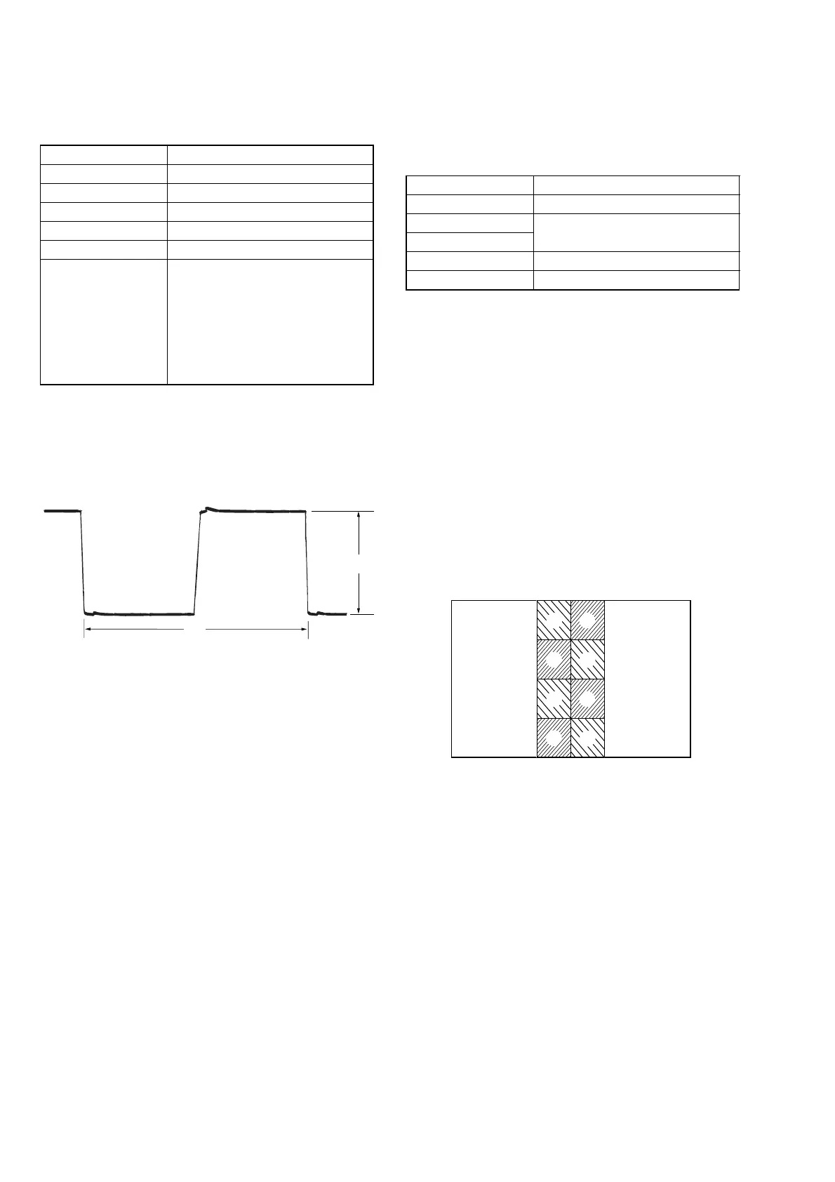
6. COM AMP Adjustment (PD-117/118 board)
Set the common electrode drive signal level of LCD to the specified
value.
Mode Camera
Subject Arbitrary
Measurement Point Pin 4 of CN5502 (PANEL COM)
Measuring Instrument Oscilloscope
Adjustment Page D
Adjustment Address A7
Specified Value A=6.33 ± 0.05 Vp-p
(2.5/3/4 LCD TYPE S model)
A=6.10 ± 0.05 Vp-p
(3.5 LCD TYPE S model)
A=5.05 ± 0.05 Vp-p
(2.5 LCD TYPE C 61 k model)
A=5.50 ± 0.05 Vp-p
(3.5/4 LCD TYPE C model)
Adjusting method:
1) Select page: 0, address: 01, and set data: 01.
2) Select page: D, address: A7, change the data and set the PANEL
COM signal level (A) to the specified value.
3) Press the PAUSE button.
4) Select page: 0, address: 01, and set data: 00.
A
A
A
A
B
B
B
B
Fig. 5-1-28
Fig. 5-1-27
A
2H
Ver. 1.1 2001. 01
 Loading...