2-5
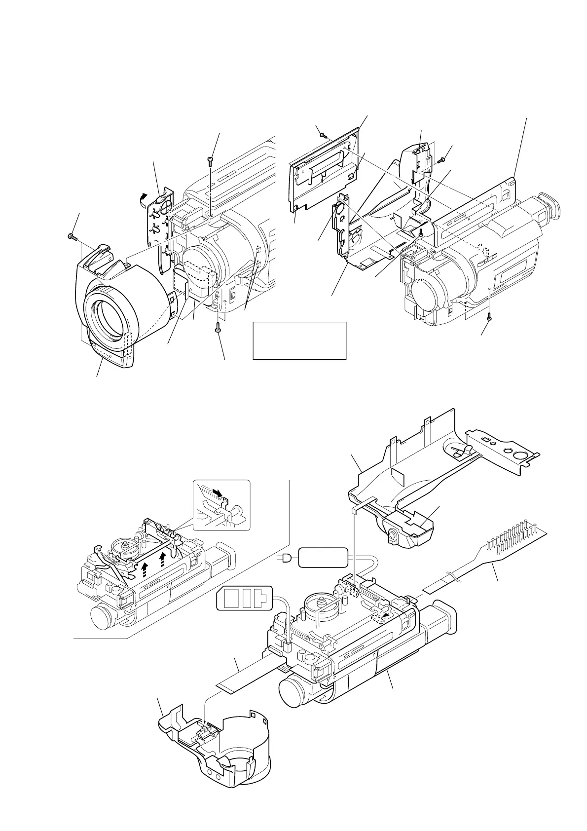
2-4. FRONT PANEL ASSEMBLY 2-5. CASSETTE LID ASSEMBLY,
CABINET (L) ASSEMBLY
[MECHANISM DECK SERVICE POSITION]
1 Screw (2 × 4)
2 Jack cover
3 Two screws
(2 × 4)
6 Front panel assembly
7 Flexible board
(CN5804)
Cushion
(SE)
4 Two screws
(2 × 4)
Note: Remove it while
taking care as
the flexible board
is connected.
5 Two claws
1 Two screws
(2 × 4)
5 Cassette lid assembly
4 Claw
0 Claw
6 Two screws
(2 × 4)
qs Flexible board
(CN253)
2 Open the control switch block.
3 Claw
9 Claw
7 Screw (2 × 4)
qa Cabinet (L) assenbly
8 Two screws
(2 × 4)
FP-159 flexible board
Adjustment remote
commander (RM-95)
Front panel assembly
A
B
• How to move up the cassette
compartment manually
Press the cassette compartment
in the direction of arrow A
to move it up in the
direction of arrow B.
AC power
adaptor
AC IN
Cabinet (R) assembly
CPC-13 jig
(J-6082-443-A)
Control switch block
(SS-10000)
Cabinet (L) assembly