5-33
Multi CPC jig
(J-6082-311-A)
Multi CPC jig
(J-6082-311-A)
PD-117 board
CN5502
6 pin
0 pin
PD-118 board
CN5502
6 pin
0 pin
Volt ohm meter
Volt ohm meter
+
–
+
–
1. LCD Initial Data Input (1)
Mode VTR stop
Signal Arbitrary
Adjustment Page C
Adjustment Address AB to BA
Adjusting method:
1) Select page: 0, address:01, and set data: 01.
2) Select page: C, and input the data in the following table.
Note: To write in the non-volatile memory (EEPROM), press
the PAUSE button of the adjustment remote commander
each time to set the data.
3) Select page: 0, address:01, and set data: 00.
1-6. LCD SYSTEM ADJUSTMENTS
Note 1: The back light (fluorescent tube) is driven by a high voltage
AC power supply. Therefore, do not touch the back light
holder to avoid electrical shock.
Note 2: When replacing the LCD unit, be careful to prevent
damages caused by static electricity.
Note 3: Set the LCD BRIGHT to the center.
Set the LCD COLOR (Menu display) to the center.
Note 4: 2.5 LCD model: DCR-TRV320/TRV320E/TRV320P
3 LCD model: DCR-TRV420E/TRV525
3.5 LCD model: DCR-TRV520/TRV520E/TRV520P/
TRV620E
4 LCD model: DCR-TRV720/TRV720E
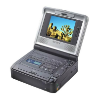
[Adjusting connector]
Most of the measuring points for adjusting the LCD display are
concentrated in the following connector.
CN5502 of the PD-117/118 board
Connect the Measuring Instruments via the multi CPC jig (J-6082-
311-A).
The following table shows the Pin No. and signal name of the
connector.
[LCD type check]
By measuring the resistor value between Pin 6 of CN5502 and Pin
q; of CN5502, the type of LCD can be discriminated.
PD-117/118 board CN5502
Abbreviation
EE : East European model
NE : North European model
RU : Russian model
HK : Hong Kong model
AUS : Australian model
CN : Chinese model
2.5 LCD model
3/3.5/4 LCD model
PD board
PD-117
PD-118
Pin No.
1
3
5
7
9
Signal Name
VB
VG
VR
C-SYNC/XHD
GND
Pin No.
2
4
6
8
10
Signal Name
XVD OUT
PANEL COM
N.C.
XHD OUT
GND
Address
Data
Remark
2.5 3 3.5/4
AB 53 53 53 Fixed data
AC 00 00 00
AD 90 90 90
AE CB CB CB
AF 66 68 6C
B0 26 28 2C
B1 00 00 00
B2 00 00 00
B3 20 20 20
B4 0A 0A 0A
B5 24 24 24
B6 1A 1A 1A
B7 08 0F 0F
B8 17 17 17
B9 21 21 21
BA 23 23 23
Resistor
value
1 kΩ
1.5 kΩ
2.2 kΩ
4.7 kΩ
5.6 kΩ
6.8 kΩ
8.2 kΩ
10 kΩ
LCD type
2.5 LCD TYPE S 61 k
2.5 LCD TYPE C 61 k
2.5 LCD
TYPE S 123 k
3 LCD TYPE S
3.5 LCD TYPE S
3.5 LCD TYPE C
4 LCD TYPE S
4 LCD TYPE C
DCR-TRV320/TRV320E/TRV320P
DCR-TRV420E/TRV520/TRV520E/TRV520P/
TRV525/TRV620E/TRV720/TRV720E
Fig. 5-1-24