5-52
2. Chroma BPF f
0
Adjustment (VC-235 board)
Set the center frequency of IC3701 chroma band-pass filter.
Mode VTR stop
Signal No signal
Measurement Point CH1: Chroma signal terminal of
S VIDEO jack (75 Ω terminated)
CH2: Y signal terminal of S VIDEO
jack (75 Ω terminated)
Measuring Instrument Oscilloscope
Adjustment Page C
Adjustment Address 28
Specified Value A = 100 mVp-p or less
B = 200 mVp-p or more
Adjusting method:
1) Select page: 0, address: 01, and set data: 01.
2) Select page: D, address: 11, set data: 10, and press the PAUSE
button of the adjustment remote commander.
3) Check that the burst signal (B) is output to the chroma signal
terminal of S VIDEO jack.
4) Select page: 3, address: 0C, set data: 04, and press the PAUSE
button.
5) Select page: C, address: 28, and change the data for minimum
amplitude of the burst signal level (A).
(The data of address: 28, should be “00” to “07”)
6) Press the PAUSE button.
7) Select page: 3, address: 0C, set data: 00, and press the PAUSE
button.
8) Check that the burst signal level (B) satisfies the specified value.
9) Select page: D, address: 11, set data: 00, and press the PAUSE
button.
10) Select page: 0, address: 01, and set data: 00.
3-4. VIDEO SYSTEM ADJUSTMENTS
3-4-1. Video System Adjustments
Adjusting Procedure:
1. 27 MHz/36 MHz origin oscillation adjustment
2. Chroma BPF f0 adjustment
3. S VIDEO OUT Y Level Adjustment
4. S VIDEO OUT chroma level adjustment
5. VIDEO OUT Y, chroma level check
6. Hi8/standard 8 mm AFC f0 adjustment
1. 27 MHz/36 MHz Origin Oscillation Adjustment
(VC-235 board)
Set the oscillation frequency of X1501.
If deviated, the synchronization will be disrupted and the color will
become inconsistent.
Note: 27 MHz ........... 720H model
36 MHz ........... 960H model
720H model: DCR-TRV320/TRV320P/TRV520/
TRV520P/TRV525/TRV720
960H model: DCR-TRV320E/TRV420E/TRV520E/
TRV620E/TRV720E
Mode Camera
Measurement Point Pin ia of IC2201
Measuring Instrument Frequency counter
Adjustment Page F
Adjustment Address 4D
Specified Value f=13500000 ± 68 Hz
Adjusting method:
1) Select page: 0, address: 01, and set data: 01.
2) Select page: F, address: 4D, change the data and set the clock
frequency(f) to the specified value.
3) Press the PAUSE button of the adjustment remote commander.
4) Select page: 0, address: 01, and set data: 00.
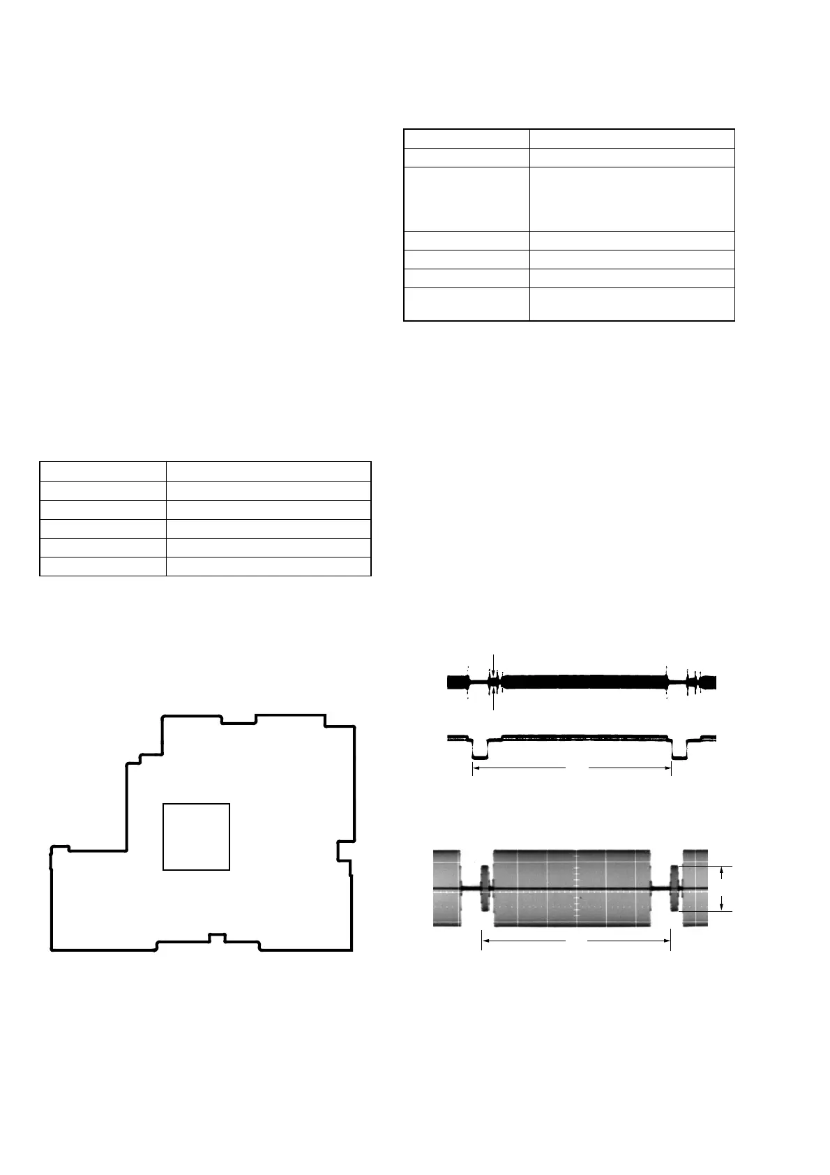
VC-235 BOARD
CH1
CH2
A
H
H
CH1 B
Fig. 5-3-9
Fig. 5-3-10
When the data of page: 3, address: 0C, is 04:
When the data of page: 3, address: 0C, is 00:
216 163
55 10881
1
54
162
109
IC2201
 Loading...