5-29
1-5. LCD ELECTRONIC VIEWFINDER SYSTEM
ADJUSTMENTS
(DCR-TRV320E: AEP, UK, EE, NE, RU/
TRV420E: AEP/TRV520E: AEP/TRV525/
TRV620E/TRV720/TRV720E)
Note 1: The back light (fluorescent tube) is driven by a high voltage
AC power supply. Therefore, do not touch the back light
holder to avoid electrical shock.
Note 2: When replacing the LCD unit, be careful to prevent
damages caused by static electricity.
Note 3: COLOR LCD EVF model:
DCR-TRV525/TRV620E/TRV720/TRV720E
B/W LCD EVF model:
DCR-TRV320E: AEP, UK, EE, NE, RU/TRV420E:
AEP/TRV520E: AEP
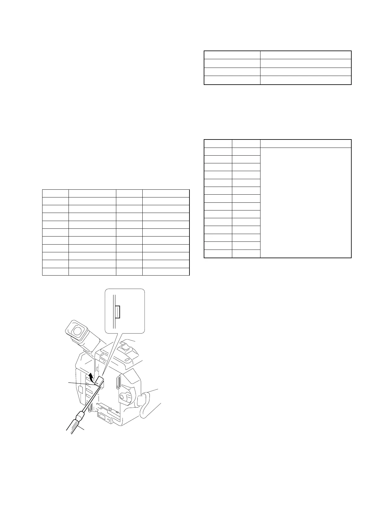
[Adjusting connector]
Most of the measuring points for adjusting the viewfinder system
are concentrated at VC-235 board CN1108. Connect the measuring
instruments via the CPC-13 jig (J-6082-443-A). The following table
lists the pin numbers and signal names of CN1108.
Address Data Remark
9B 4C Fixed data
9C 00
9D A0
9E CE
9F 64
A0 24
A1 00
A2 80
A3 12
A4 0C
A5 25
A6 00
A7 08
A8 18
1. EVF Initial Data Input (1)
Mode VTR stop
Signal Arbitrary
Adjustment Page C
Adjustment Address 9B to A8
Adjusting method:
1) Select page: 0, address:01, and set data: 01.
2) Select page: C, and input the data in the following table.
Note: To write in the non-volatile memory (EEPROM), press
the PAUSE button of the adjustment remote commander
each time to set the data.
3) Select page: 0, address:01, and set data: 00.
CN1108
1
20
Cover
Screw driver (–)
Pin No.
1
2
3
4
5
6
7
8
9
10
Signal Name
SWP
AFC F0
BPF MONI
F0 ADJ RF IN
PB RF
REG GND
RF AGC OUT
VC RF SWP
EVF BL
EVF BL 4.6V
Pin No.
11
12
13
14
15
16
17
18
19
20
Signal Name
VCO
EVF VG
DV RF SWP
RF IN
CAP FG
RF MON
TMS
TCK
TDO
TDI
Fig. 5-1-21