55
HCD-HPX7
SECTION 6
ELECTICAL ADJUSTMENTS
DECK SECTION
1. Demagnetize the record/playback head with a head
demagnetizer.
2. Do not use a magnetized screwdriver for the adjustments.
3. After the adjustments, apply suitable locking compound to
the parts adjust.
4. The adjustments should be performed with the rated power
supply voltage unless otherwise noted.
5. The adjustments should be performed for both L-CH and R-
CH.
6. Switches and controls should be set as follows unless otherwise
specified.
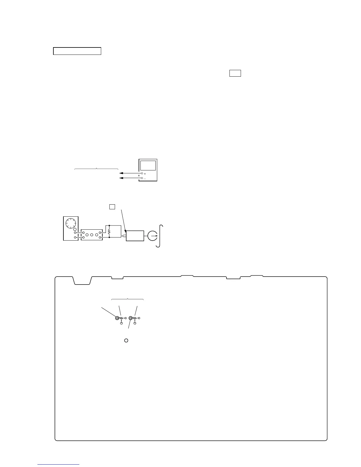
REC BIAS ADJUSTMENT
Setting:
Procedure:
1. Connect a digital voltmeter (AC range) to TP101 (L), TP201
(R) and TP (GND) on the MAIN board.
2. Insert a blank tape (CS-123).
3. Press the ?/1 button to turn the power on, and press the
[FUNCTION] button to select TAPE function.
4. Press the [ REC] button twice to start recording.
5. Adjust RV101 (L-ch), RV201 (R-ch) on the MAIN board so
that the digital voltmeter reads AC 6.15 V.
6. Connect an oscilloscope or frequency counter to TP101 (L),
TP201 (R) and TP (GND) on the MAIN board.
7. Confirm that the frequency is 82 kHz ±3 kHz.
Mode: REC
MAIN board
digital voltmeter
(AC range)
TP101 (L), TP201 (R)
TP (GND)
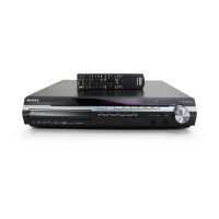
– MAIN BOARD (Conductor Side) –
RV201 RV101
TP (GND)
REC BIAS ADJUSTMENT
(R-CH) (L-CH)
TP201 (R)
TP101 (L)
AF OSC
JACK (J321)
blank tap
e
CS-123
set
attenuator
600
Ω
i
z
Adjustment Location: