Version 5.2 Sourcefire 3D System Installation Guide 35
Understanding Deployment
Connecting Devices to Your Network
Chapter 2
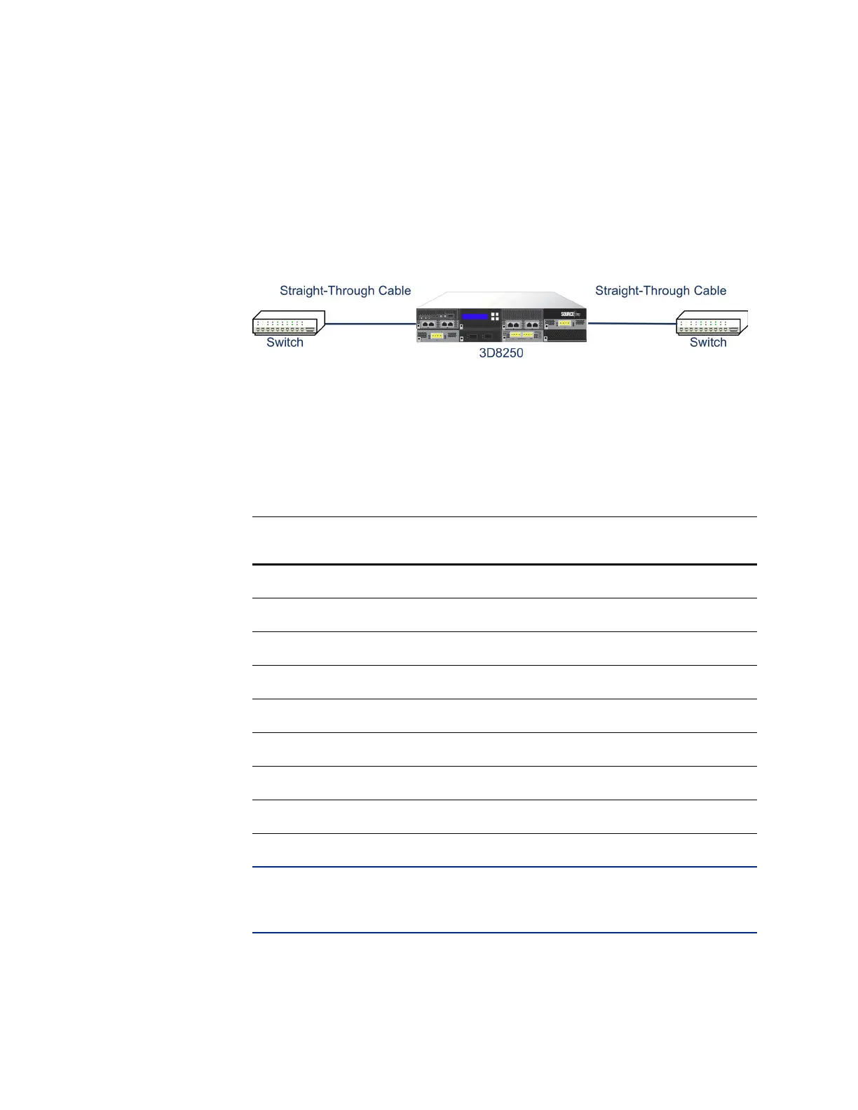
For a managed device that bypasses with a crossover connection, wire the device
as would normally be done without a device deployed. The link should work with
power to the device removed. In most cases you should use two straight-through
cables to connect the device to the two endpoints.
Crossover Bypass Connection Cabling
The Valid Configurations for Hardware Bypass and table indicates where you
should use crossover or straight-through cables in your hardware bypass
configurations. Note that a Layer 2 port functions as a straight-through (MDI)
endpoint in the deployment, and a Layer 3 port functions as a crossover (MDIX)
endpoint in the deployment. The total crossovers (cables and appliances) should
be an odd number for bypass to function properly.
IMPORTANT! In the Valid Configurations for Hardware Bypass table, = indicates
a straight-through cable or managed device bypass connection, and X indicates a
crossover cable or managed device bypass connection.
Note that every network environment is likely to be unique, with endpoints that
have different combinations of support for Auto-MDI-X. The easiest way to
Valid Configurations for Hardware Bypass
ENDPOINT 1 CABLE MANAGED
D
EVICE
CABLE ENDPOINT 2
MDIX===MDI
MDIX==MDI
MDI==XMDI
MDI===MDIX
MDIX=X=MDIX
MDI = X = MDI
MDIXXXMDI
MDIXXX=MDI