www.spacelabshealthcare.com
4-10
91390
QUBE
M AINTENANCE
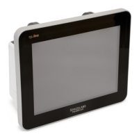
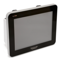
Figure 4-4 Bezel Assembly and Rear Enclosure
5 Start from the bottom and disconnect the three black wire
bundles from the monitor side. Refer to Figure 4-4.
6 Remove the video cable P/N 175-1856-00 from the monitor.
7 Disconnect the remaining black ribbon cable from the monitor
side. Refer to Figure 4-4.
8 Remove bezel assembly.
Reassembly
1 Position the new bezel assembly as shown in Figure 4-4.
2 Connect cable 175-1855-xx Com4 to J941 (CPU).
3 Connect cable Center Video Port 175-1858-xx to J40 (CPU).
4 Connect cable 175-1856-xx to J261 (CPU).
5 Connect cable 175-1857-xx Com1 to J50 (CPU).
175-1855-xx Com4 to J941 (CPU)
Touch Screen
Flat Ribbon Cable - P341 (CPU)
Center Video Port
175-1858-xx - J40 (CPU)
Center Video
Port - J40
(CPU)
175-1857-xx Com1 to J50 (CPU)
175-1857-xx Com1 to
J50 (CPU)
175-1856-xx to J261 (CPU)
Caution:
Use caution when handling the cables. The cables are fragile and can
easily be damaged.
 Loading...