www.spacelabshealthcare.com
4-30
91390
QUBE
M AINTENANCE
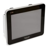
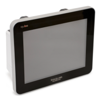
Figure 4-26 Docking Connector Plug
Removal of Pod Interface PCBA for Options A and B
Refer to Drawing 7 for details and find the replacement assembly kit
listed with the Parts List on page 6-2.
1 Power OFF the monitor and remove the battery or batteries.
2 Remove the module from the monitor.
3 Disconnect the POD interface cable (Item 14).
4 Use a right-angle Phillips head screw driver to remove the six
screws (items 27) while you hold the POD interface bracket (item
48) to the rear enclosure.
5 Remove the POD interface bracket. Do not remove the "Ball
Stud" clips.
6 Remove the four terminal washers (items 18).
7 You can gently pull on the PCBA if necessary, as there is a gasket
sealing the PCB to the rear enclosure.
8 Inspect the POD interface PCBA gasket and "Ball Studs" for any
visible damage. Replace them if necessary.
Reinstallation of the Pod Interface PCBA
1 Before you install the new POD interface PCBA again, make sure
that the POD interface gaskets and ball studs are not damaged.
Replace them as necessary.
2 If not already completed, attach the POD interface gaskets (Items
38 and 39) to the rear enclosure.
3 Place the monitor on a flat surface, so that the display side faces
up. Place the POD Interface PCBA and terminal washers in their
respective locations.
4 Place the two "Ball Stud" clips (Item 36) in place, and the use the
six screws (Items 27) to attach the POD Interface bracket (Item
48).
5 Reconnect the POD interface cable (Item 14).
6 Perform the retest procedure. Refer to Monitor Functional Tests
on page 4-5.
 Loading...