www.spacelabshealthcare.com
4-11
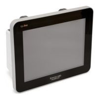
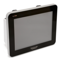
91390 QUBE
M AINTENANCE
Figure 4-5 Connect the cables
6 To attach the bezel assembly to the rear enclosure with the 10
original screws. Be careful not to over-tighten the screws.
Note:
The bezel and rear enclosure must align on the bottom of the
monitor. The bottom edge of the enclosure must fit into the
bezel. Be careful not to pinch any cables, especially the touch
screen cable.
7 Install the eight finishing plugs removed in Step 2 on page 4-8.
8 Perform the functional test procedure. Refer to Monitor
Functional Tests on page 4-5.
CPU PCB
1 Perform Step 1 on page 4-8 though Step 8 on page 4-10.
Notes:
• If the wireless option is not installed, skip to Step 6 on page 4-
12.
• The replacement CPU PCB does not come with a new wireless
adaptor PCB. Remove the wireless adaptor card and install it
on the new CPU PCB.
2 To remove the two antenna cables from the wireless card, use the
003-0286-00 antenna extraction tool as shown in Figure 4-6.
Caution:
Use caution when handling the two antenna cables. The cables are fragile
and can easily be damaged.
 Loading...