www.spacelabshealthcare.com
4-12
91390
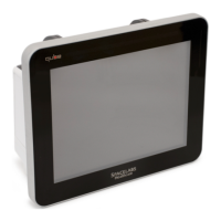
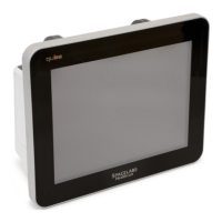
QUBE
M AINTENANCE
Figure 4-6 Wireless Antenna Cables
3 Gently press outward on the retaining clips that hold the wireless
adaptor card in place. Remove the wireless adaptor board.
4 Set aside the wireless adaptor PCB for installation on the
replacement CPU PCB. Use proper ESD protection.
5 Disconnect the fan cable from the CPU PCB.
6 Remove the 12 screws that secure the CPU PCB to the chassis.
Notes:
• Do not remove the screw that secures the USB daughter
board to the CPU PCB. Refer to Figure 4-6.
• The CPU PCB is press fitted onto the connectors, for the
interface, monitor dock, and battery PCBs.
7 Remove the old CPU PCB. Gently pull the CPU away from the
interface, monitor dock, and battery PCB connectors.
8 Disconnect the speaker cable from the back-side of the CPU PCB.
9 To replace the USB card, remove the screw that attaches the old
USB to the CPU PCB. Install the new USB card. Refer to Figure 4-
7 on page 4-13.
Notes:
• If you replace the USB daughter card, format and configure it.
Refer to the XPREZZON and qube System Administration
Manual (P/N 070-2380-xx).
Adaptor Clips
Do not
remove USB
daughter
board screw
Fan Cable
 Loading...