www.spacelabshealthcare.com
2-3
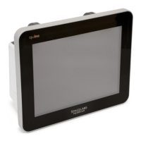
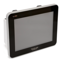
91390 QUBE
S ETUP
Input/Output Connections (Internal and External)
This section defines the I/O connections.
The back panel includes:
•DC Input Power connector
• SDLC (Flexport) connector
• Pod interface connector (SDLC protocol): options A and B
• Remote Nurse Alert connector: option A
• Second display connector (DVI-D)
• RS232 serial connector
• USB ports: Four for option A. Two for options B and C.Ethernet
10/100 base T, RJ45 connector.
The left side supports the module slot. The right side accommodates
two lithium batteries and the recorder.
Pod Interface Connector - 8
CONTACT PADS for options A
and B
The pod interface SDLC I/O connector (P300) is on the back panel
of the monitor. The pinout for this connector is designed as follows:
Warning:
Data interface connectors on this device are Ground (Earth) referenced!
- Only connect this device to other medical equipment suitable for
use in the Patient Vicinity.
- Check Ground (Earth) Leakage after connecting data interface
cables.
Table 2-1 Pinout for Pod Interface Connectors
Pin # Function
PIN 1 SDLC_DAT+
PIN 2 SDLC_DAT-
PIN 3 SDLC_CLK+
PIN 4 SDLC_ CLK +
PIN 5 GROUND
PIN 6 +5 VDC
PIN 7 +12 VDC
PIN 8 -12 VDC
 Loading...