9-2 Sequencing Logic
605C Frequency Inverter
Note: 1. Jogging is set TRUE once the jog cycle has started, and remains TRUE until the
jog cycle has finished which is when either the stop delay has finished or
another mode is demanded.
2. Stopping is set TRUE during the stopping cycles commanded by either RUN
going low, JOG going low or if Fast Stop is active.
3. Once Run and Jog are both FALSE, HEALTHY O/P will be set TRUE.
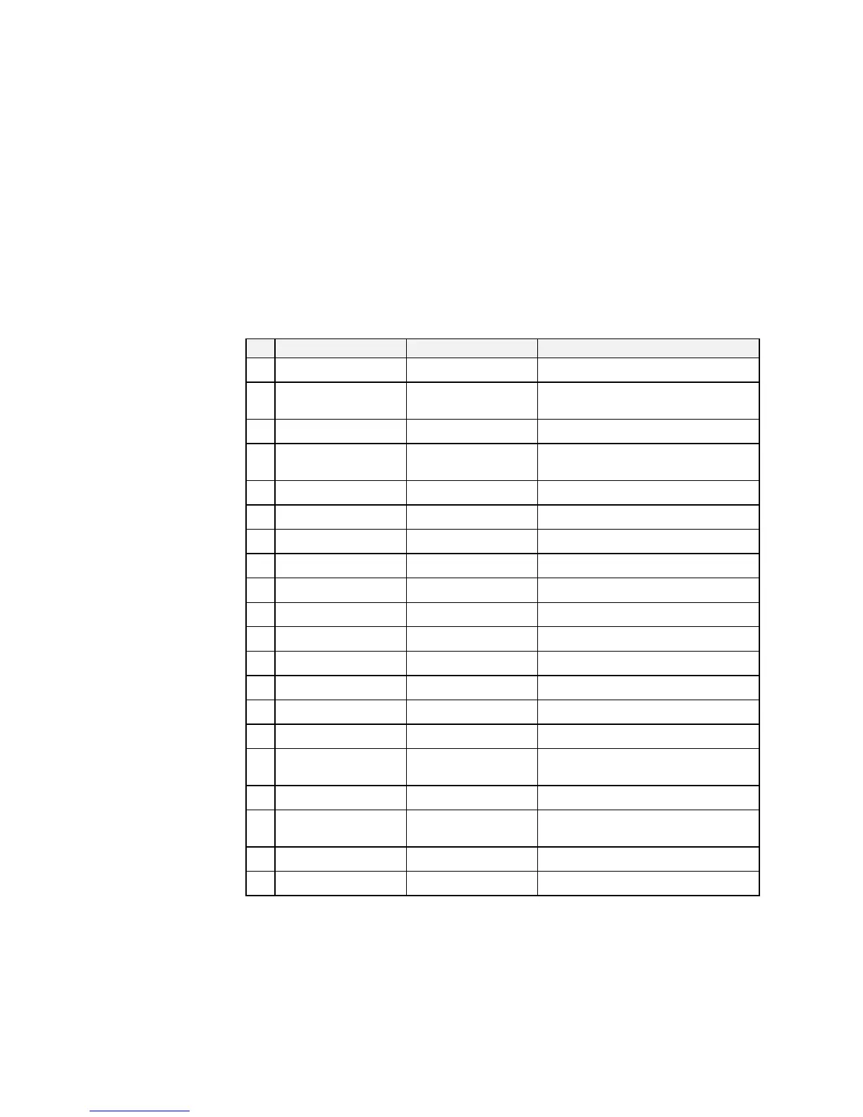
Transition of States
The transition matrix describes what causes the transition from one state to another, for example
see no. 5 below: the transition from “Ready To Switch On” to “Trip Active” is triggered by
“TRIP” going TRUE.
Refer to the following table and state diagram.
Current State Next State Cause (FALSE to TRUE)
1 Power Up Not Ready To Switch On Reset OR initialise
2 Not Ready To Switch On Switch On Disabled Initialise complete AND NOT re-
configuration mode
3 Switch On Disabled Trip Active Trip
4 Switch On Disabled Ready To Switch On NOT Run AND NOT Jog AND /Fast-Stop
AND /Coast-Stop
5 Ready To Switch On Trip Active Trip
6 Ready To Switch On Switch On Disabled NOT /Coast-Stop OR NOT /Fast-Stop
7 Ready To Switch On Switched On Run OR Jog
8 Switched On Trip Active Trip
9 Switched On Switch On Disabled NOT /Coast-Stop OR NOT /Fast-Stop
10 Switched On Ready To Switch On NOT Run AND NOT Jog
11 Switched On Enabled Inverter Enable
12 Enabled Trip Active Trip
13 Enabled Switch On Disabled NOT /Coast Stop
14 Enabled Fast Stop Active NOT /Fast Stop
15 Enabled Switched On NOT Inverter Enable
16 Enabled Ready To Switch On NOT Run AND NOT Jog
AND stop sequence complete
17 Fast Stop Active Trip Active Trip
18 Fast Stop Active Switch On Disabled Fast Stop timer expired OR Fast Stop Mode
= Coast Stop OR Inverter at zero setpoint
19 Trip Active Tripped Stack quenched
20 Tripped Switch On Disabled NOT Trip AND Trip Reset 0->1 transition
Table 9-3 Transition Matrix