Installing the Inverter 3-7
605C Frequency Inverter
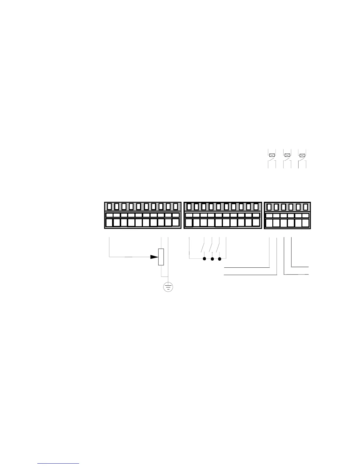
Control Wiring Connections
Note: Use screened control cables to comply with EMC requirements.
1. Feed the control cables into the inverter through the metal gland plate and connect to the
control terminals. The diagram below shows the typical control connections required for
operation as a simple speed controller.
2. Refit and secure the terminal cover using the retaining screws.
Note: Refer to Chapter 11: “Technical Specifications” for Control Terminal information
Refer to Chapter 6: “Programming Your Application” for ANALOG INPUT and ANALOG
OUTPUT 1 configuration switch settings.
HEALTH
Speed Setpoint
10
k
220V AC 3A maximum
TB1
TB3 TB4
into a resistive load (default)
12345678910
11 12 13 14 15 16 17 18 19 20
DOUT1_A
DOUT1_B
DOUT2_A
DOUT2_B
DOUT3_A
DOUT3_B
21 22 23 24 25 26
AIN1 (SPEED SETPOINT)
AIN2 (SETPOINT TRIM)
AIN3
0
V
AIN4
AOUT1 (RAMP OUTPUT)
AOUT2
+10V REF
0
V
-10V REF
+24VC
0V
DIN1 (RUN)
DIN2 (TRIP RESET)
DIN3 (DIR)
DIN4 (EXT TRIP)
DIN5 (JOG)
DIN6
DIN7
DIN8
RUNNING
Figure 3-9 Typical Connection to the Control Terminals (as Macro 1)