Certification for the Inverter 12-7
605C Frequency Inverter
Requirements for UL Compliance
Solid-State Motor Overload Protection
These devices provide Class 10 motor overload protection. The maximum internal overload
protection level (current limit) is 150% for 60 seconds, and for quadratic torque 110% for 10
seconds. Refer to Chapter 6: Programming Your Application - I*t TRIP for user current limit
adjustment information.
An external motor overload protective device must be provided by the installer where the motor
has a full-load ampere rating of less than 50% of the Inverter output rating.
Short Circuit Rating
All models of this Inverter are suitable for use on a circuit capable of delivering not more than
10,000 RMS Symmetrical Amperes, 460V maximum.
Solid-State Short-Circuit Protection
These devices are provided with Solid-State Short-Circuit (output) Protection. Branch circuit
protection requirements must be in accordance with the latest edition of the National Electrical
Code NEC/NFPA-70.
Recommended Branch Circuit Protection
It is recommended that UL Listed (JDDZ) non-renewable cartridge fuses, Class K5 or H; or UL
Listed (JDRX) renewable cartridge fuses, Class H, are installed upstream of the Inverter. Refer
to Chapter 11: “Technical Specifications” - Power Details for recommended fuse ratings.
Motor Base Frequency
The motor base frequency rating is 480Hz maximum.
Field Wiring Temperature Rating
Use 75°C Copper conductors only.
Field Wiring Terminal Markings
For correct field wiring connections that are to be made to each terminal refer to Chapter 3:
“Installing the Inverter” - Power Wiring Connections, and Control Wiring Connections.
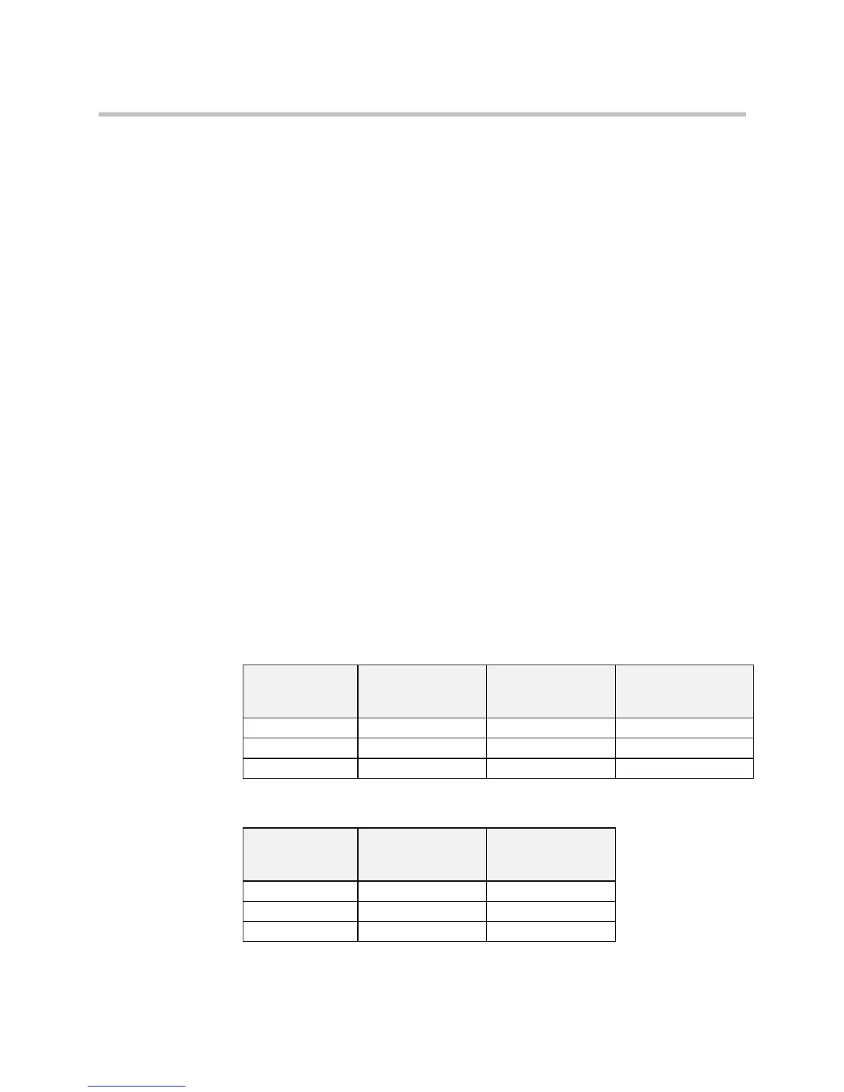
Power Wiring Terminals
Model Recognition
Product Code
(Block 2 & 3)
Power Terminals
(maximum wire size)
Brake Terminals
(maximum wire size)
Thermistor Terminals
(maximum wire size)
0055/400 12 AWG (3.3mm²) 12 AWG (3.3mm²) 12 AWG (3.3mm²)
0075/400 8 AWG (8.4mm²) 12 AWG (3.3mm²) 12 AWG (3.3mm²)
0110/400 8 AWG (8.4mm²) 12 AWG (3.3mm²) 12 AWG (3.3mm²)
Terminal Tightening Torque
Model Recognition
Product Code
(Block 2 & 3)
Power Terminals
(lb-in)
Brake Terminals
(lb-in)
0055/400 12 12
0075/400 16 12
0110/400 16 12