6-6 Programming Your Application
605C Frequency Inverter
ANALOG DIGIN
The analog digital input block allows the analog input terminals to be used as digital input
signals.
Functional Description
The Inverter has two analog inputs. There is a digital analog input function block for each:
ANALOG DIGIN 1 is associated with the signal on terminal 1, whilst ANALOG DIGIN 2 is
associated with the signal on terminal 2.
The analog digital input function blocks allow the analog terminals to be used as digital inputs
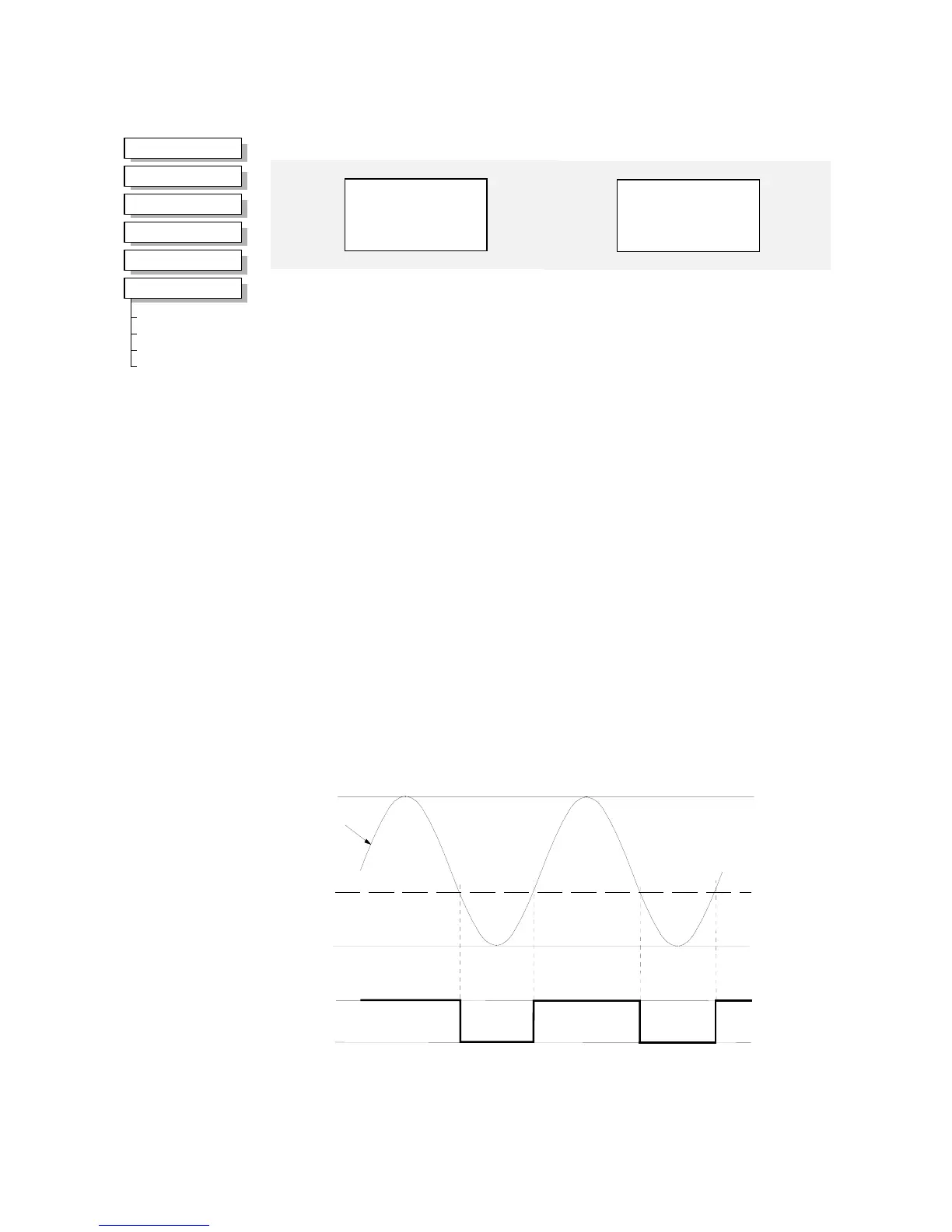
where extra digital inputs are required. The input voltage or current is converted to a TRUE or
FALSE digital signal. Generally, (when INVERT is FALSE), an input greater than the
comparison LEVEL will cause the output VALUE to be TRUE. Similarly, an input less than the
comparison LEVEL will cause the output VALUE to be FALSE.
+10V
-10V
0%
30%
100%
0 (FALSE)
1 (TRUE)
LEVEL
TRUE
FALSE
VALUE
raw input
MMI Menu Map
1
SETUP PARAMETERS
2
FUNCTION BLOCKS
3
INPUTS & OUTPUTS
4
ANALOG DIGIN
5
ANALOG DIGIN 1
5
ANALOG DIGIN 2
A DIN 2 INVERT
A DIN 2 LEVEL
A DIN 2 HYST
A DIN 2 VALUE
ANALOG DIGIN 2
VALUE [95] – FALSE
FALSE – [94] INVERT –
30.00 % – [96] LEVEL –
5.00 % – [97] HYSTERISIS –
Parameter Descriptions
INVERT
Range: FALSE / TRUE
When this is TRUE, the VALUE output is inverted.
LEVEL
Range: 0.00 to 100.00 %
This is the level used to determine whether the input is high or low. The actual level also
depends on the hardware range selected.
HYSTERISIS
Range: 0.00 to 50.00 %
A hysterisis value used to prevent jitter on the input. The actual hysterisis also depends on the
hardware range selected.
VALUE
Range:FALSE / TRUE
A TRUE or FALSE output depending on the input volts or current.
ANALOG DIGIN 1
VALUE [ 90] – FALSE
FALSE – [ 89] INVERT –
30.00 % – [ 91] LEVEL –
5.00 % – [ 92] HYSTERISIS –