Programming Your Application 6-25
605C Frequency Inverter
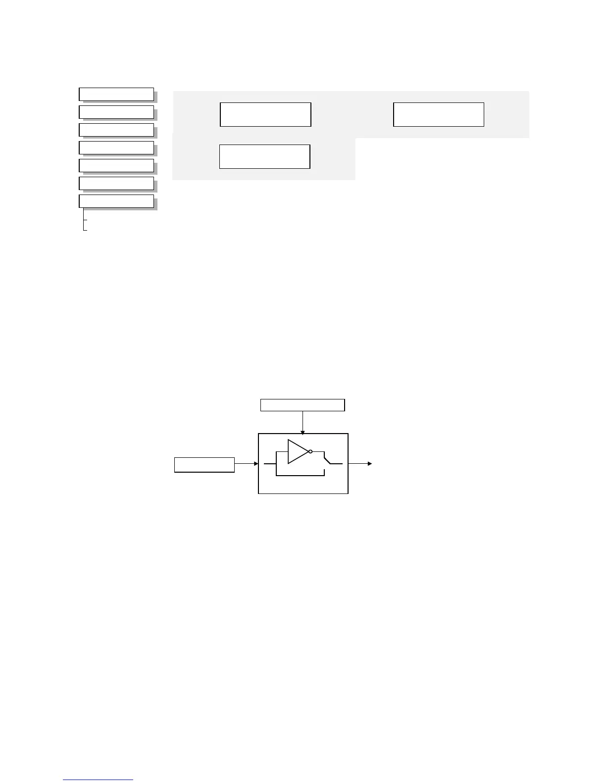
DIGITAL OUTPUT
The digital output block converts a logic TRUE or FALSE demand to a physical output signal.
Functional Description
The Inverter has three physical digital outputs (volt-free relay contacts). There is a DIGITAL
OUTPUT function block associated with each of these:
DIGITAL OUTPUT 1 is associated with terminals 21 & 22
DIGITAL OUTPUT 2 is associated with terminals 23 & 24
DIGITAL OUTPUT 3 is associated with terminals 25 & 26
INVERT reverses the output logic.
MMI Menu Map
1
SETUP PARAMETERS
2
FUNCTION BLOCKS
3
INPUTS & OUTPUTS
4
DIGITAL OUTPUT
5
DIGITAL OUTPUT 1
5
DIGITAL OUTPUT 2
5
DIGITAL OUTPUT 3
DOUT 3 VALUE
DOUT 3 INVERT
DIGITAL OUTPUT 2
FALSE – [ 55] VALUE
–
FALSE
–
[ 54] INVERT
–
DIGITAL OUTPUT 1
FALSE – [ 52] VALUE
–
FALSE
–
[ 51] INVERT
–
DIGITAL OUTPUT 3
FALSE – [737] VALUE
–
FALSE
–
[736] INVERT
–
Parameter Descriptions
VALUE
Range: FALSE / TRUE
The TRUE or FALSE output demand.
INVERT
Range: FALSE / TRUE
Controls the optional inversion of the VALUE output.
OUTPUT
INVERT
VALUE