Operating the Inverter 4-3
605C Frequency Inverter
Note: Start/Stop is also known as “Sequencing”.
Speed Control is also known as “Reference Generation”.
Selecting Local or Remote Control
If the default combination of remote Start/Stop and Speed Control is not suitable for your
application, follow the instructions below using the Operator Station or a suitable PC
programming tool to select suitable combinations of local or remote control.
Note: You can only change between Local and Remote control when the Inverter is “stopped”.
To change a combination the Operator Station must have the “Advanced” viewing level
selected; allowing you to view enough of the menu structure to make the change. Refer to
Chapter 5: “ The Operator Station” - Menu Viewing Levels.
The L/R key on the Operator Station toggles between Local and Remote control, changing both
Start/Stop and Speed Control modes at the same time.
However, you can “fix” either or both modes in software to be either Local or Remote control.
This makes the L/R key inoperative for that mode. In this way, you can select a combination
where both Local and Remote modes are present.
To do this, go to the LOCAL CONTROL menu at level 4 and select
either:
LOCAL ONLY Sets Local control
REMOTE ONLY Sets Remote control
LOCAL/REMOTE Gives selection powers back to the L/R key.
Fixing only one of the modes will mean that the L/R key will still
toggle the other mode between Local and Remote control.
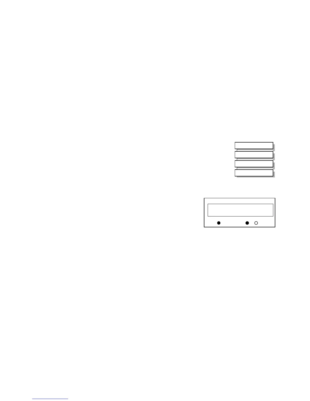
LED Indications
The mode of control is indicated by the
“LOCAL” LEDs on the Operator Station:
SEQ = Start/Stop
REF = Speed Control
If the LED is illuminated ( ● ), then LOCAL
mode is in force.
Note: The default is for the L/R key to be operative for both Sequencing and Reference
Generation, and to be set for Remote control, i.e. both LEDs will be off.
MMI Menu Map
1
SETUP PARAMETERS
2
FUNCTION BLOCKS
3
SEQ & REF
4
LOCAL CONTROL
HEALTH
LOCAL
SEQ
REF
SEQ MODES
LOCAL ONLY
Figure 4-3 Control Mode LED Indications