An Overview of the Inverter 2-1
605C Frequency Inverter
2 AN OVERVIEW OF THE INVERTER
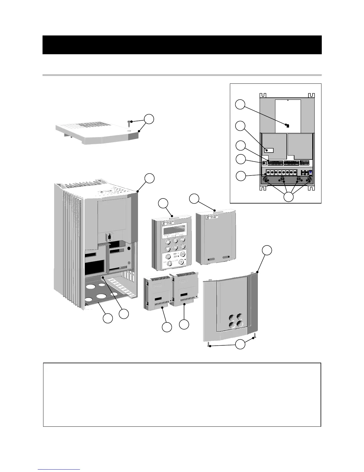
Component Identification
2
7
8
15
14
4
13
12
9
5
10
11
Front View (with items removed)
1
6
3
16
Figure 2-1 View of Component Parts
1 Main inverter assembly 9 Control terminals
2 Top cover and screw (optional) 10 Power terminals
3 Terminal cover retaining screw 11 Earthing points
4 Terminal cover 12 RS232 programming port
5 Remote operator station port 13 Gland plate
6 Power terminal shield 14 Comms technology option (optional)
7 6051 operator station (optional) 15 Speed feedback technology option (optional)
8 Blank cover 16 Configuration switches SW1 & SW2